# Boards & Kits

# STM32 Nucleo

## Board

- [https://en.wikipedia.org/wiki/STM32#Development\_boards](https://en.wikipedia.org/wiki/STM32#Development_boards)
- [NUCLEO-F302R8](http://www.st.com/content/st_com/en/products/evaluation-tools/product-evaluation-tools/mcu-eval-tools/stm32-mcu-eval-tools/stm32-mcu-nucleo/nucleo-f302r8.html) board for [STM32F302R8T6](http://www.st.com/content/st_com/en/products/microcontrollers/stm32-32-bit-arm-cortex-mcus/stm32f3-series/stm32f302/stm32f302r8.html) MCU with 72 MHz **Cortex-M4F** core, 64 KB flash, 16 KB SRAM.<sup class="reference" id="bkmrk-"></sup>
- RAM: `0x20000000` (16 KiB)
- FLASH: `0x08000000` (64 KiB)
- Start address (entry point): `0x08000400`

## Documentation

- [https://os.mbed.com/platforms/ST-Nucleo-F302R8/#getting-started](https://os.mbed.com/platforms/ST-Nucleo-F302R8/#getting-started)
- [MCU Reference manual](https://wiki.hexadust.net/attachments/9)
- [Board User manual](https://wiki.hexadust.net/attachments/11)

## Software - Void Linux

1. Install software ```
    xi stlink
    ```
2. Set up udev rules (as root)  
    ```
    #/etc/udev/rules.d/stm32nucleo.rules
    SUBSYSTEM!="usb|usb_device", ACTION!="add", GOTO="stm32nucleo_end"
    ATTRS{idVendor}=="0483", ATTRS{idProduct}=="374b", SYMLINK+="stm32-%k", MODE="660", GROUP="input"
    LABEL="stm32nucleo_end"
    ```
3. Connect device
4. Probe for the device `st-info --probe`; should print something like this:  
    ```
    Found 1 stlink programmers
      version:    V2J33S25
      serial:     066FFF5155xxxxxxxxxxxxx
      flash:      65536 (pagesize: 2048)
      sram:       40960
      chipid:     0x439
      dev-type:   STM32F301_F302_F318
    ```
5. Read boot or flash area  
    ```
    st-flash read /tmp/boot.bin 0x0 0x10000 # flash if booting from flash
    st-flash read /tmp/flash.bin 0x8000000 0x10000 # flash
    ```

### Debugging

1. Install tools  
    ```
     xi cross-arm-none-eabi cross-arm-none-eabi-gdb
    ```
2. Using GDB 
    1. Connect to device  
        ```
        st-util
        ```
    2. Run GDB  
        ```
        arm-none-eabi-gdb -ex 'target extended-remote localhost:4242'
        ```

Using OpenOCD

1. Install  
    ```
    xi openocd inetutils-telnet
    ```
2. Run server  
    ```
    openocd -f interface/stlink.cfg -f target/stm32f3x.cfg
    ```
3. It should print something like  
    ```
    Info : STLINK V2J33M25 (API v2) VID:PID 0483:374B
    Info : Target voltage: 3.238345
    Info : [stm32f3x.cpu] Cortex-M4 r0p1 processor detected
    Info : [stm32f3x.cpu] target has 6 breakpoints, 4 watchpoints
    ```
4. Now you can telnet to the debugger: `telnet localhost 4444`  
    ```
    halt
    reg
    # read output register of port B
    read_memory 0x48000414 32 1
    # disable LED on PB-13
    write_memory 0x48000414 32 0x0
    # enable LED on PB-13
    write_memory 0x48000414 32 0x2000
    ```
5. Or use **gdb**: `arm-none-eabi-gdb -ex 'target extended-remote :3333'`

## Rust

- [https://docs.rust-embedded.org/book/start/qemu.html](https://docs.rust-embedded.org/book/start/qemu.html)

Tools:

```
rustup target add thumbv7em-none-eabihf
rustup component add llvm-tools-preview
cargo install cargo-binutils
cargo install cargo-generate
```

### Template project

```
cargo generate --git https://github.com/rust-embedded/cortex-m-quickstart
```

Edit `.cargo/config.toml` and comment other and un-comment `target = "thumbv7em-none-eabihf"     # Cortex-M4F and Cortex-M7F (with FPU)` .

Edit `memory.x`:

```
MEMORY
{
  /* NOTE 1 K = 1 KiBi = 1024 bytes */
  FLASH : ORIGIN = 0x08000000, LENGTH = 64K
  RAM : ORIGIN = 0x20000000, LENGTH = 16K
}
```

Set up **openocd**, edit: `openocd.cfg`:

```
source [find interface/stlink.cfg]
source [find target/stm32f3x.cfg]
```

It should now build:

```
cargo build
cargo readobj -- --file-headers
```

To see assembly (look for `00000484 <main>`:):

```
cargo objdump --release -- --disassemble --no-show-raw-insn --print-imm-hex
```

### QEMU

Install QEMU:

```
xi qemu libnuma
```

Build example program:

```rust
#![no_std]
#![no_main]

use panic_halt as _;
use cortex_m_rt::entry;
use cortex_m_semihosting::{debug, hprintln};

#[entry]
fn main() -> ! {
    hprintln!("Hello, world!").unwrap();

    // exit QEMU
    // NOTE do not run this on hardware; it can corrupt OpenOCD state
    debug::exit(debug::EXIT_SUCCESS);

    loop {}
}
```

Build:

```
cargo build --release
```

Run (note we are using `netduinoplus2` device as it uses M4 CPU as well, see: [https://qemu.readthedocs.io/en/master/system/arm/stm32.html](https://qemu.readthedocs.io/en/master/system/arm/stm32.html)):

```
qemu-system-arm \
  -cpu cortex-m4 \
  -machine netduinoplus2 \
  -nographic \
  -semihosting-config enable=on,target=native \
  -kernel target/thumbv7em-none-eabihf/release/stm32-nucleo-test
```

It should print `Hello, world!`.

Can also setup `cargo run` to run in QEMU in `.cargo/config.toml`:

```
[target.thumbv7em-none-eabihf]
runner = "qemu-system-arm -cpu cortex-m4 -machine netduinoplus2 -nographic -semihosting-config enable=on,target=native -kernel"
```

### Debugging on hardware

Run `openocd`, it should print like:

```
Info : [stm32f3x.cpu] Cortex-M4 r0p1 processor detected
Info : [stm32f3x.cpu] target has 6 breakpoints, 4 watchpoints
Info : starting gdb server for stm32f3x.cpu on 3333
Info : Listening on port 3333 for gdb connections
Info : accepting 'gdb' connection on tcp/3333
```

Connect debugger pointing it to the built binary (cargo build --release):

```
arm-none-eabi-gdb -ex 'target extended-remote :3333' -q target/thumbv7em-none-eabihf/release/stm32-nucleo-test
```

Now you can flash the program using `load` command and run with `cont`.

If using **semihosting** (to print stuff in **openocd** window from the device), enable support with `monitor arm semihosting enable` before running the program.

Can also setup `cargo run` to run on device in `.cargo/config.toml`:

```
[target.'cfg(all(target_arch = "arm", target_os = "none"))']
runner = "arm-none-eabi-gdb -q -x openocd.gdb"
```

### HAL

For STM32F302R8T6 MCU we can use `stm32f302x8` feature of [stm32f3xx-hal crate](https://crates.io/crates/stm32f3xx-hal) (x denotes any a to z) see: [https://docs.rs/stm32f3xx-hal/latest/stm32f3xx\_hal/#target-chip-selection](https://docs.rs/stm32f3xx-hal/latest/stm32f3xx_hal/#target-chip-selection).

Example `Cargo.toml`:

```
[package]
authors = ["Jakub Pastuszek <jpastuszek@protonmail.com>"]
edition = "2018"
readme = "README.md"
name = "stm32-nucleo-test"
version = "0.1.0"

[dependencies]
cortex-m = { version = "0.7.7", features = ["critical-section-single-core"]}
cortex-m-rt = "0.7.3"
cortex-m-semihosting = "0.5.0"
critical-section = "1.1.2"
panic-halt = "0.2.0"
panic-semihosting = "0.6.0"
stm32f3xx-hal = { version = "0.10.0", features = ["stm32f302x8", "rt"] }

# Uncomment for the panic example.
# panic-itm = "0.4.1"

# Uncomment for the allocator example.
# alloc-cortex-m = "0.4.0"

[[bin]]
name = "stm32-nucleo-test"
test = false
bench = false

[profile.release]
codegen-units = 1 # better optimizations
debug = true # symbols are nice and they don't increase the size on Flash
lto = true # better optimizations
```

Blinking LED2, `src/main.rs`:

```rust
#![no_std]
#![no_main]

use cortex_m::asm;
use cortex_m_rt::entry;
// pick a panicking behavior
// use panic_halt as _; // you can put a breakpoint on `rust_begin_unwind` to catch panics
// use panic_abort as _; // requires nightly
// use panic_itm as _; // logs messages over ITM; requires ITM support
use cortex_m_semihosting::{dbg, hprintln};
use panic_semihosting as _; // logs messages to the host stderr; requires a debugger

use stm32f3xx_hal::{self as hal, pac, prelude::*};

#[entry]
fn main() -> ! {
    let dp = pac::Peripherals::take().unwrap();

    let mut rcc = dp.RCC.constrain();
    let mut gpiob = dp.GPIOB.split(&mut rcc.ahb);

    let mut led2 = gpiob
        .pb13
        .into_push_pull_output(&mut gpiob.moder, &mut gpiob.otyper);

    loop {
        // hprintln!("Hello, world!");
        led2.toggle().unwrap();
        asm::delay(1_000_000);
    }
}
```

More examples: [https://github.com/stm32-rs/stm32f3xx-hal/tree/master/examples](https://github.com/stm32-rs/stm32f3xx-hal/tree/master/examples)

# Smart switch ESP8266EX

## Sonoff WiFi smart switch

![IMG_20241022_181937.jpg](https://wiki.hexadust.net/uploads/images/gallery/2024-10/scaled-1680-/dt92UGvfYN2Xcv1R-img-20241022-181937.jpg)

- Original firmware: [fwbackup.bin](https://wiki.hexadust.net/attachments/32)
- Installing alternative firmware: [https://tasmota.github.io/docs/Getting-Started/](https://tasmota.github.io/docs/Getting-Started/)

[![IMG_20241022_175313_566_2.jpg](https://wiki.hexadust.net/uploads/images/gallery/2024-10/scaled-1680-/HNJb1QLmTvOno1np-img-20241022-175313-566-2.jpg)](https://wiki.hexadust.net/uploads/images/gallery/2024-10/HNJb1QLmTvOno1np-img-20241022-175313-566-2.jpg)

Input for the board is from mains. It is then rectified and transformed down to 3.3V via DS1117 regulator to power the ESP8266EX chip and the relay that switches the mains relay.

- [3.3V regulator](https://wiki.hexadust.net/attachments/31)

Marked are 3.3V VCC and GND. The ESP8266EX UART-0 is on marked points TX and RX.

- [ESO8266EX datasheet](https://wiki.hexadust.net/attachments/30)

[![IMG_20241022_175313_566_1.jpg](https://wiki.hexadust.net/uploads/images/gallery/2024-10/scaled-1680-/hfminf3YCcsVZJmF-img-20241022-175313-566-1.jpg)](https://wiki.hexadust.net/uploads/images/gallery/2024-10/hfminf3YCcsVZJmF-img-20241022-175313-566-1.jpg)

### [![1000007682.jpg](https://wiki.hexadust.net/uploads/images/gallery/2024-10/scaled-1680-/Mf9t4PMUyyB9mbSO-1000007682.jpg)](https://wiki.hexadust.net/uploads/images/gallery/2024-10/Mf9t4PMUyyB9mbSO-1000007682.jpg)

### Boot message

```
 ets Jan  8 2013,rst cause:4, boot mode:(3,6)

wdt reset
```

### Flashing

While holding the button connect the USB UART.

```
$ esptool.py -p /dev/ttyUSB0 flash_id
esptool.py v4.5.1
Serial port /dev/ttyUSB0
Connecting...
Detecting chip type... Unsupported detection protocol, switching and trying again...
Connecting...
Detecting chip type... ESP8266
Chip is ESP8266EX
Features: WiFi
Crystal is 26MHz
MAC: 5c:cf:7f:xx:xx:xx
Stub is already running. No upload is necessary.
Manufacturer: 5e
Device: 4014
Detected flash size: 1MB
Hard resetting via RTS pin...
```

Backup original firmware and erase flash.

```
$ esptool.py -p /dev/ttyUSB0 read_flash 0x00000 0x100000 fwbackup.bin
...
1048576 (100 %)
1048576 (100 %)
Read 1048576 bytes at 0x00000000 in 96.5 seconds (86.9 kbit/s)...
Hard resetting via RTS pin...

$ esptool.py -p /dev/ttyUSB0 erase_flash
...
Erasing flash (this may take a while)...
Chip erase completed successfully in 52.8s
Hard resetting via RTS pin...
```

Now power cycle with button pressed again to enter programming mode.

```
$ esptool.py -p /dev/ttyUSB0 write_flash -fm dout 0x0 tasmota.bin
....
Configuring flash size...
Flash will be erased from 0x00000000 to 0x000a2fff...
Compressed 665504 bytes to 475418...
Wrote 665504 bytes (475418 compressed) at 0x00000000 in 41.9 seconds (effective 127.0 kbit/s)...
Hash of data verified.

Leaving...
Hard resetting via RTS pin...
```

### Connecting via UART

```
$ tio /dev/ttyUSB0 -e -m ONLCRNL
00:00:00.002 HDW: ESP8266EX
00:00:00.017-031 CFG: Use defaults
00:00:00.577 QPC: Reset
00:00:00.591 Project tasmota - Tasmota Version 14.3.0(release-tasmota)-2_7_7(2024-10-15T08:18:01)
00:00:00.951 WIF: WifiManager active for 3 minutes
00:00:00.461 HTP: Web server active on tasmota-79E7BE-1982 with IP address 192.168.4.1
00:06:50.536 CMD: status
00:06:50.542 RSL: STATUS = {"Status":{"Module":1,"DeviceName":"Tasmota","FriendlyName":["Tasmota"],"Topic":"tasmota_79E7BE","ButtonTopic":"0","Power":"0","PowerLock":"0","PowerOnState":3,"LedState":1,"LedMask":"FFFF","SaveData":0,"SaveState":1,"SwitchTopic":"0","SwitchMode":[0,0,0,0,0,0,0,0,0,0,0,0,0,0,0,0,0,0,0,0,0,0,0,0,0,0,0,0],"ButtonRetain":0,"SwitchRetain":0,"SensorRetain":0,"PowerRetain":0,"InfoRetain":0,"StateRetain":0,"StatusRetain":0}}
```

Try typing `status` and enter.

## Configuration

### WiFi  


The device can be connected to via WiFi directly or configured via UART. WiFi configuration did not work for me, it was getting a timeout... looks like there is an issue with testing 'N' wireless while staying in AP mode (AP+STA)?

I had issues with device not able to connect (needed 3-4 restarts), disabling *Short Preamble* and changing channel to 1 on my AP improved chances to connect.

Via UART type and hit enter: `Backlog <ssid>; password1 <pass>`

```
00:09:45.138 RSL: RESULT = {"Password1":"<pass>"}
00:09:46.504 APP: Restarting

 ets Jan  8 2013,rst cause:1, boot mode:(3,6)

load 0x4010f000, len 3584, room 16
tail 0
chksum 0xb0
csum 0xb0
v3969889e
~ld

00:00:00.002 HDW: ESP8266EX
00:00:00.054 CFG: Loaded from flash at F7, Count 29
00:00:00.060 QPC: Count 1
00:00:00.071 Project tasmota - Tasmota Version 14.3.0(release-tasmota)-2_7_7(2024-10-15T08:18:01)
00:00:01.166 WIF: Connecting to AP1 <ssid> in mode 11n as tasmota-79E7BE-1982...
00:00:06.559 QPC: Reset
00:00:09.791 WIF: Connected
00:00:10.043 HTP: Web server active on tasmota-79E7BE-1982 with IP address 192.168.80.206
17:58:21.023 RSL: INFO1 = {"Info1":{"Module":"Sonoff Basic","Version":"14.3.0(release-tasmota)","FallbackTopic":"cmnd/DVES_79E7BE_fb/","GroupTopic":"cmnd/tasmotas/"}}
17:58:21.029 RSL: INFO2 = {"Info2":{"WebServerMode":"Admin","Hostname":"tasmota-79E7BE-1982","IPAddress":"192.168.80.206"}}
17:58:21.039 RSL: INFO3 = {"Info3":{"RestartReason":"Software/System restart","BootCount":13}}
17:58:21.047 RSL: RESULT = {"POWER":"OFF"}
17:58:21.051 RSL: POWER = OFF
17:58:25.476 RSL: STATE = {"Time":"2024-10-26T17:58:25","Uptime":"0T00:00:17","UptimeSec":17,"Heap":27,"SleepMode":"Dynamic","Sleep":50,"LoadAvg":19,"MqttCount":0,"POWER":"OFF","Wifi":{"AP":1,"SSId":"<ssid>","BSSId":"62:D7:9A:61:55:DE","Channel":11,"Mode":"11n","RSSI":100,"Signal":-44,"LinkCount":1,"Downtime":"0T00:00:11"}}
```

### Timezone

Use web console or UART:

- List of commands for given time zone: https://tasmota.github.io/docs/Timezone-Table/
- For Ireland/Dublin:

```
Backlog0 Timezone 99; TimeStd 1,0,3,1,1,60; TimeDst 1,0,10,1,2,0
```

# Lilygo LORA32 - TinyGS

## [![lilygo_LORA32.jpg](https://wiki.hexadust.net/uploads/images/gallery/2024-12/scaled-1680-/9wE48T1YCidzLx9T-lilygo-lora32.jpg)](https://wiki.hexadust.net/uploads/images/gallery/2024-12/9wE48T1YCidzLx9T-lilygo-lora32.jpg)

ESP32: [esp32\_technical\_reference\_manual\_en\_0.pdf](https://wiki.hexadust.net/attachments/47)

## Configuration

Configuration can be reset using UART (`e` to reset configuration).

<p class="callout info">In my case the display would turn off after initial loading screen. This can be fixed by configuring "OLED Bright" configuration option (e.g. to 50).</p>

After reset the device sets up Wi-Fi AP at `My TinyGS` and can be reached at [http://192.168.4.1/](http://192.168.4.1/).

# Raspberry Pi Pico H

## Specs

- Dual core Arm Cortex M0+ 133 MHz
- 264kB multi-bank high performance SRAM
- 2MiB external flash
- Datasheet: [pico-datasheet.pdf](https://wiki.hexadust.net/attachments/51)

### Pinout

- `VBUS` **40** - micro-USB input voltage, connected to micro-USB port pin 1. This is nominally 5V (or 0V if the USB is not  
    connected or not powered).
- `VSYS` **39** - main system input voltage, which can vary in the allowed range 1.8V to 5.5V, and is used by the on-board  
    SMPS to generate the 3.3V for the RP2040 and its GPIO.
- `GND` **38** - ground.
- UART TX **1** / RI **2**
- `LED` (`GP25`) - LED is connected to GPIO 25.

## [![pico-pinout.png](https://wiki.hexadust.net/uploads/images/gallery/2024-12/scaled-1680-/vO9Xd85WyfglJ6a0-pico-pinout.png)
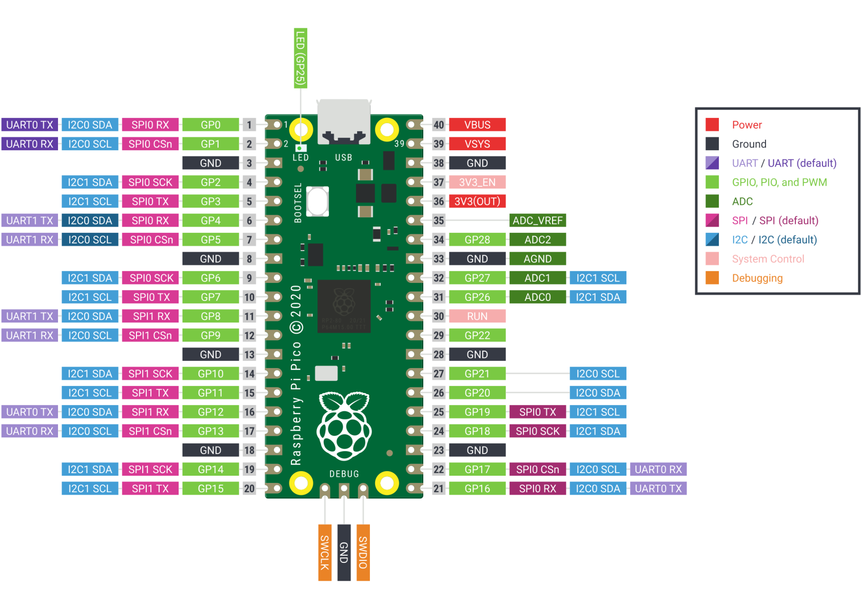
](https://wiki.hexadust.net/uploads/images/gallery/2024-12/vO9Xd85WyfglJ6a0-pico-pinout.png)Rust

### Dependencies

```bash
rustup target install thumbv6m-none-eabi
cargo install flip-link
cargo install --locked elf2uf2-rs
```

Set up mount point for RP2 device in `/etc/fstab`:

```
LABEL="RPI-RP2" /mnt/rp2 auto defaults,user,noauto,nosuid,nodev,noexec 0 0
```

### Template project setup

Template project: [https://github.com/rp-rs/rp2040-project-template](https://github.com/rp-rs/rp2040-project-template)

1. Uncomment `elf2uf2-rs -d` runner in `.cargo/config.toml`: ```diff
    diff --git a/.cargo/config.toml b/.cargo/config.toml
    index a565984..04a72c4 100644
    --- a/.cargo/config.toml
    +++ b/.cargo/config.toml
    @@ -2,8 +2,8 @@
     # Choose a default "cargo run" tool (see README for more info)
     # - `probe-rs` provides flashing and defmt via a hardware debugger, and stack unwind on panic
     # - elf2uf2-rs loads firmware over USB when the rp2040 is in boot mode
    -runner = "probe-rs run --chip RP2040 --protocol swd"
    -# runner = "elf2uf2-rs -d"
    +#runner = "probe-rs run --chip RP2040 --protocol swd"
    +runner = "elf2uf2-rs -d"
    
     rustflags = [
       "-C", "linker=flip-link",
    ```
2. Connect (while holding `BOOTSEL` button) and mount RP2 device: `mount /mnt/rp2`
3. Build and run: `cargo run --release`

# zeptoforth

- Install doc: [https://github.com/tabemann/zeptoforth/wiki/Installing-and-Building-zeptoforth-and-Using-the-zeptoforth-Console](https://github.com/tabemann/zeptoforth/wiki/Installing-and-Building-zeptoforth-and-Using-the-zeptoforth-Console "Installing and Building zeptoforth and Using the zeptoforth Console")
    - Download latest release from tag: [https://github.com/tabemann/zeptoforth/releases](https://github.com/tabemann/zeptoforth/releases)
    - Untar
    - Press **bootsel** and plug in Pico and mount USB volume
    - Copy `zeptoforth_full_usb-*.uf2` from `bin/*/rp2040_big` to Pico USB volume
    - Use `tio /dev/ttyACM0` to connect to Forth console

# Arduino Nano - Atmel MEGA328P

## Pinout

[![Arduino-Nano-Pinout-Large.png](https://wiki.hexadust.net/uploads/images/gallery/2024-12/scaled-1680-/R6ZtvvBFPpVNeDfS-arduino-nano-pinout-large.png)
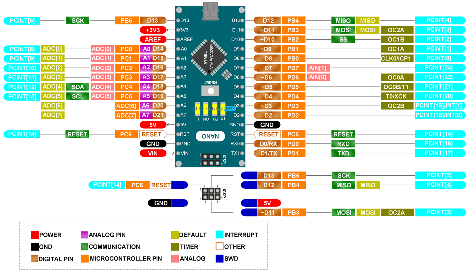
](https://wiki.hexadust.net/uploads/images/gallery/2024-12/R6ZtvvBFPpVNeDfS-arduino-nano-pinout-large.png)

- 5V - comes form USB-C VBUS and/or output of the regulator (VIN); MCU has operating voltage of 1.8 - 5.5V
- VIN - goes to the regulator and can be maximum 15 V; minimum 5 + ~1.1 (dropout) for regulator to regulate; MCU should run with 2.9 V
- 3V3 - output from USB-UART
- D13/PB5 is connected to LED

<details id="bkmrk-schematics"><summary>Schematics</summary>

![1ee669b8983149d48d41557d41e3fcb1.png](https://wiki.hexadust.net/uploads/images/gallery/2024-12/scaled-1680-/JzuORuvMSETUol5q-1ee669b8983149d48d41557d41e3fcb1.png)

</details>
## Atmel MEGA328P

- <span class="parametrics-key">Clock: 16 MHz</span>
- <span class="parametrics-key">Program Memory Size: </span><span class="parametrics-value">32 KiB</span>
- <span class="parametrics-key">RAM: </span><span class="parametrics-value">2 </span>KiB
- <span class="parametrics-key">Data EEPROM:</span><span class="parametrics-value"> 1 KiB</span>

[![atmega.jpg](https://wiki.hexadust.net/uploads/images/gallery/2024-12/scaled-1680-/7USYZ539xBdLo43z-atmega.jpg)](https://wiki.hexadust.net/uploads/images/gallery/2024-12/7USYZ539xBdLo43z-atmega.jpg)

Datasheet: [ATmega48A-PA-88A-PA-168A-PA-328-P-DS-DS40002061B.pdf](https://wiki.hexadust.net/attachments/54)

## LM1117C 50 - 5V regulator

[![arduino_nano_lm.jpg](https://wiki.hexadust.net/uploads/images/gallery/2024-12/scaled-1680-/HHQmAbjF8lTminS3-arduino-nano-lm.jpg)](https://wiki.hexadust.net/uploads/images/gallery/2024-12/HHQmAbjF8lTminS3-arduino-nano-lm.jpg)

Datasheet: [lm1117.pdf](https://wiki.hexadust.net/attachments/55)

### CH340C - USB-UART

Datasheet: [CH340DS1.PDF](https://wiki.hexadust.net/attachments/58)

## Programming  


### Arduino / avrdude

Install IDE (and `avrdude`):

```
xi arduino
```

The board shows up on `/dev/ttyUSB0` and can be programmed with `CTRL-R` (**Compile/Verify**) and `CTRL-U` (**Upload**).

### Rust

- [https://book.avr-rust.org/](https://book.avr-rust.org/)
- [https://github.com/avr-rust/awesome-avr-rust](https://github.com/avr-rust/awesome-avr-rust)
- [https://github.com/Rahix/avr-hal](https://github.com/Rahix/avr-hal)

```
cargo +stable install --locked ravedude
cargo install cargo-generate
cargo generate --git https://github.com/Rahix/avr-hal-template.git # Select: Arduino Nano New Bootloader

# May need specific compiler version to work (see rust-toolchain.toml)
rustup override set nightly-2024-03-22
rustup component add rust-src --toolchain nightly-2024-03-22-x86_64-unknown-linux-gnu

cargo build
RAVEDUDE_PORT=/dev/ttyUSB0 cargo run
```

# Sinclair Scientific Calculator Emulator (1974)

[e![sinclair_scientific.jpg](https://wiki.hexadust.net/uploads/images/gallery/2024-12/scaled-1680-/y07viwwZBHEX5yzO-sinclair-scientific.jpg)](https://wiki.hexadust.net/uploads/images/gallery/2024-12/y07viwwZBHEX5yzO-sinclair-scientific.jpg)[![SC0.jpg](https://wiki.hexadust.net/uploads/images/gallery/2025-01/scaled-1680-/evc0HjqnmrcZantn-sc0.jpg)](https://wiki.hexadust.net/uploads/images/gallery/2025-01/evc0HjqnmrcZantn-sc0.jpg)

> A register level TMS0805 CPU emulator on an Arduino Nano runs the original 320 instruction calculator program. A custom PCB houses it all.

## Resources

- [Reversing Sinclair's amazing 1974 calculator hack](http://files.righto.com/calculator/sinclair_scientific_simulator.html "Reversing Sinclair's amazing 1974 calculator hack")  
    > Now Texas Instruments offered him an inexpensive [calculator chip](http://righto.com/ti) that could barely do four-function math. Could he use this chip to build a $100 scientific calculator? Texas Instruments' engineers said this was impossible - their chip only had 3 storage registers, no subroutine calls, and no storage for constants such as π. The ROM storage in the calculator held only 320 instructions, just enough for basic arithmetic. How could they possibly squeeze any scientific functions into this chip?
    > 
    > Fortunately Clive Sinclair, head of Sinclair Radionics, had a secret weapon - programming whiz and math PhD Nigel Searle. In a few days in Texas, they came up with new algorithms and wrote the code for the world's first single-chip scientific calculator, somehow programming sine, cosine, tangent, arcsine, arccos, arctan, log, and exponentiation into the chip. The engineers at Texas Instruments were amazed.
- [Project page &amp; build instructions: Sinclair Scientific Calculator Emulator](https://hackaday.io/project/91895-sinclair-scientific-calculator-emulator)

## Schematics

[![V5 Schematic.png](https://wiki.hexadust.net/uploads/images/gallery/2024-12/scaled-1680-/72h8SHcPhxQ4983a-v5-schematic.png)](https://wiki.hexadust.net/uploads/images/gallery/2024-12/72h8SHcPhxQ4983a-v5-schematic.png)

> This is a custom PCB shape. A 50x100mm rectangle with 3mm radius corners.

## Power

The switch is connected to VIN ping on Arduino Nano, so it goes to the 5V regulator that can handle up to 15V and has ~1.1V dropout. With MCU needing 1.8V at minimum, the board should be supplied with at least 2.9V.

- With 3xAA batteries: 
    - 4.35V *VIN*, I get 3.27V on *5V* pin; so ~1.1V dropout on the regulator.
    - 4.32V directly to 5V pin will let it run longer on batteries as there is no dropout of the regulator; 3V3 pin shows 3.27V; but this would bypass the switch

## Programming

The board uses [Arduino Nano](https://wiki.hexadust.net/books/electronics/page/arduino-nano-atmel-mega328p):

- Software: [https://gitlab.com/arduinoenigma/ArduinoNanoSinclairScientificCalculator/-/tree/master?ref\_type=heads](https://gitlab.com/arduinoenigma/ArduinoNanoSinclairScientificCalculator/-/tree/master?ref_type=heads)
    - Use [https://gitlab.com/arduinoenigma/ArduinoNanoSinclairScientificCalculator/-/blob/master/SinclairScientific7/SinclairScientific7.ino?ref\_type=heads](https://gitlab.com/arduinoenigma/ArduinoNanoSinclairScientificCalculator/-/blob/master/SinclairScientific7/SinclairScientific7.ino?ref_type=heads) ([SinclairScientific7.ino](https://wiki.hexadust.net/attachments/56))
    - Add library ZIP (**Sketch** / **Include Library** / **Add .ZIP Library...)** from: [https://gitlab.com/arduinoenigma/ArduinoNanoSinclairScientificCalculator/-/blob/master/SinclairScientific1/libraries/Arduino-GPIO-master.zip?ref\_type=heads](https://gitlab.com/arduinoenigma/ArduinoNanoSinclairScientificCalculator/-/blob/master/SinclairScientific1/libraries/Arduino-GPIO-master.zip?ref_type=heads) ([SinclairScientific7.ino](https://wiki.hexadust.net/attachments/56))
    - I have changed serial settings on line 310 to use standard baud rate but note that it may not work for your board as it is badly timed at 16MHz clock (see [https://wormfood.net/avrbaudcalc.php](https://wormfood.net/avrbaudcalc.php))  
        ```diff
        diff --git a/SinclairScientific7/SinclairScientific7.ino b/SinclairScientific7/SinclairScientific7.ino
        index 487d8f2..ec2e143 100644
        --- a/SinclairScientific7/SinclairScientific7.ino
        +++ b/SinclairScientific7/SinclairScientific7.ino
        @@ -307,7 +307,7 @@ void setup()
         {
           // put your setup code here, to run once:
        
        -  Serial.begin(2000000);
        +  Serial.begin(115200);
        
           // makes it easier to see if an arduino is programmed or not
           Serial.print(F("SINCLAIR v7 092318"));
        ```

After using IDE to build and upload you can connect to it via UART to get hello message:

```bash
hxd@morgana ~> tio /dev/ttyUSB0
[22:06:24.423] tio v2.7
[22:06:24.423] Press ctrl-t q to quit
[22:06:24.424] Connected
SINCLAIR v7 092318 -Common Anode -Aligned Right
```

- Alternative software calculator implementation in Rust: [https://gitea.hexadust.net/hxd/sinclair-sci-calc](https://gitea.hexadust.net/hxd/sinclair-sci-calc)

## Box

I have designed a box with battery and Arduino USB port access for easy battery replacement and programming or USB power.

<p class="callout warning">USB port access assumes that Arduino board was soldered with a distance from the main board - this is to avoid having to cut Arduino board header pins leaving sharp edges.</p>

[![SC2.jpg](https://wiki.hexadust.net/uploads/images/gallery/2025-01/scaled-1680-/42JspfN3yyvnhto3-sc2.jpg)](https://wiki.hexadust.net/uploads/images/gallery/2025-01/42JspfN3yyvnhto3-sc2.jpg)![SC3.jpg](https://wiki.hexadust.net/uploads/images/gallery/2025-01/scaled-1680-/ViIR8u3usWrOjWHT-sc3.jpg)[![SC5.jpg](https://wiki.hexadust.net/uploads/images/gallery/2025-01/scaled-1680-/hrVObYKPVgunpHQl-sc5.jpg)](https://wiki.hexadust.net/uploads/images/gallery/2025-01/hrVObYKPVgunpHQl-sc5.jpg)[![SC4.jpg](https://wiki.hexadust.net/uploads/images/gallery/2025-01/scaled-1680-/jrfdg8anrRoSdjnw-sc4.jpg)](https://wiki.hexadust.net/uploads/images/gallery/2025-01/jrfdg8anrRoSdjnw-sc4.jpg)

- FreeCAD model (see *Spreadsheet* for tuning): [Sinclair\_Scientific.FCStd](https://wiki.hexadust.net/attachments/75)
- Exported models: 
    - USB-C:  
        
        - [Sinclair\_Scientific-Body-USB-C.stl](https://wiki.hexadust.net/attachments/79)
        - [Sinclair\_Scientific-USB Door-USB-C.stl](https://wiki.hexadust.net/attachments/72)
    - USB mini-B: 
        - [Sinclair\_Scientific-Body-USB-mini-B.stl](https://wiki.hexadust.net/attachments/77)
        - [Sinclair\_Scientific-USB-mini-B.3mf](https://wiki.hexadust.net/attachments/73)
    - Common: 
        - [Sinclair\_Scientific-Battery Door.stl](https://wiki.hexadust.net/attachments/69)
        - [Sinclair\_Scientific-Battery pack holder.stl](https://wiki.hexadust.net/attachments/71)
- PrusaSlicer project: 
    - USB-C: [Sinclair\_Scientific-USB-C.3mf](https://wiki.hexadust.net/attachments/74)
    - USB min-B: [Sinclair\_Scientific-USB-mini-B.3mf](https://wiki.hexadust.net/attachments/73)

### Printing

Make sure that main body has supports printed under the battery door area. The battery pack holder goes inside the box on top of the battery pack to prevent it getting pushed in when replacing the batteries. Before assembly use lubricant on sides and on the latches of the battery doors for smooth operation.

Object scaling (may vary from printer to printer and printing settings):

- For battery bay doors use 99% scale for sides axis (y), 99.8% for length (x) and 98% for thickness (z).
- For USB doors use 99% scale for all axis.

[![2025-01-23-183704.png](https://wiki.hexadust.net/uploads/images/gallery/2025-01/scaled-1680-/fkD9BkvoGjGHhuLo-2025-01-23-183704.png)](https://wiki.hexadust.net/uploads/images/gallery/2025-01/fkD9BkvoGjGHhuLo-2025-01-23-183704.png)

## Usage

As per [User Manual](https://wiki.hexadust.net/attachments/61):

- Enter firs number followed by `+` or `-` for negative number (`0+<number>`)
- Use `E` key to start entering exponent - 2 numbers can be entered, further presses overwrite entered numbers; press `-` before entering numbers for negative exponent
- Enter second number
- Select operation (press up or down arrow followed by operation for alternative operation)

<table border="1" id="bkmrk-number-key-sequence-" style="border-collapse: collapse; width: 99.9841%; height: 881.817px;"><colgroup><col style="width: 47.7378%;"></col><col style="width: 33.7293%;"></col><col style="width: 18.4967%;"></col></colgroup><tbody><tr style="height: 29.8px;"><td style="height: 29.8px;">**Calculation**  
</td><td style="height: 29.8px;">**Key Sequence**  
</td><td style="height: 29.8px;">**Result Display** </td></tr><tr style="height: 29.8px;"><td colspan="3" style="height: 29.8px;">**Basic input**  
</td></tr><tr style="height: 29.9667px;"><td style="height: 29.9667px;">`592`  
</td><td style="height: 29.9667px;">`592E2+`  
</td><td style="height: 29.9667px;">` 5.9200 00`  
</td></tr><tr style="height: 29.9667px;"><td style="height: 29.9667px;">`4.29`  
</td><td style="height: 29.9667px;">`429+`  
</td><td style="height: 29.9667px;">` 4.9200 00`  
</td></tr><tr style="height: 29.9667px;"><td style="height: 29.9667px;">`0.0037`  
</td><td style="height: 29.9667px;">`037E-2+`  
</td><td style="height: 29.9667px;">` 3.7000-03`  
</td></tr><tr style="height: 30.2px;"><td style="height: 30.2px;">`0.5673*10<sup>-12</sup>`  
</td><td style="height: 30.2px;">`05673E-12+`  
</td><td style="height: 30.2px;">` 5.6730-13`  
</td></tr><tr style="height: 30.2px;"><td style="height: 30.2px;">`6.7*10<sup>-3</sup>` (`0.0067`)  
</td><td style="height: 30.2px;">`067E-2+`  
</td><td style="height: 30.2px;">` 6.7000-03`  
</td></tr><tr style="height: 29.8px;"><td colspan="3" style="height: 29.8px;">**<span class="expandableItem">Reverse Polish notation</span>**  
</td></tr><tr style="height: 29.9667px;"><td style="height: 29.9667px;">`18*((4.5-3.2)/7)`  
</td><td style="height: 29.9667px;">`45+32-7%18E1x`  
</td><td style="height: 29.9667px;">` 3.3427 00`  
</td></tr><tr style="height: 30.2px;"><td style="height: 30.2px;">`(0.326-0.583)*1.48*10<sup>7</sup>`  
</td><td style="height: 30.2px;">`0326+0583-148E7x`  
</td><td style="height: 30.2px;">`-3.8936 06`  
</td></tr><tr style="height: 31.9167px;"><td colspan="3" style="height: 31.9167px;">**Logarithm (log<sub>10</sub>)**  
</td></tr><tr style="height: 29.9667px;"><td style="height: 29.9667px;">`log 1`  
</td><td style="height: 29.9667px;">`1⮝x`  
</td><td style="height: 29.9667px;">` 0.0000 00`  
</td></tr><tr style="height: 29.9667px;"><td style="height: 29.9667px;">`log 3.6`  
</td><td style="height: 29.9667px;">`36⮝x`  
</td><td style="height: 29.9667px;">` 5.5634-01`  
</td></tr><tr style="height: 29.9667px;"><td style="height: 29.9667px;">`log 71000`  
</td><td style="height: 29.9667px;">`71E4⮝x`  
</td><td style="height: 29.9667px;">` 4.8512 00`  
</td></tr><tr style="height: 29.9667px;"><td style="height: 29.9667px;">`log 10`  
</td><td style="height: 29.9667px;">`1E1⮝x`  
</td><td style="height: 29.9667px;">` 1.0000 00`  
</td></tr><tr style="height: 31.9167px;"><td colspan="3" style="height: 31.9167px;">**Natural logarithm (log<sub>e</sub>) - Multiply by log<sub>e</sub>10 (`ln10 2.30259`)**  
</td></tr><tr style="height: 33.3667px;"><td style="height: 33.3667px;">`log<sub>e</sub>5`  
</td><td style="height: 33.3667px;">`5⮝x23026x`  
</td><td style="height: 33.3667px;">` 1.6095 00`  
</td></tr><tr style="height: 32.05px;"><td colspan="3" style="height: 32.05px;">**Anti-logarithm (10<sup>x</sup>) - input from `0.0` to `99.999`, error aprox `0.001`**  
</td></tr><tr style="height: 30.2px;"><td style="height: 30.2px;">`10<sup>0</sup>`  
</td><td style="height: 30.2px;">`0⮟x`  
</td><td style="height: 30.2px;">` 1.0000 00`  
</td></tr><tr style="height: 29.9667px;"><td style="height: 29.9667px;">`sqrt 10`  
</td><td style="height: 29.9667px;">`05⮟x`  
</td><td style="height: 29.9667px;">` 3.1621 00`  
</td></tr><tr style="height: 30.2px;"><td style="height: 30.2px;">`10<sup>1.5</sup>`  
</td><td style="height: 30.2px;">`15⮟x`  
</td><td style="height: 30.2px;">` 3.1621 01`  
</td></tr><tr style="height: 30.2px;"><td style="height: 30.2px;">`10<sup>67.5</sup>`</td><td style="height: 30.2px;">`675E1⮟x`  
</td><td style="height: 30.2px;">` 3.1621 67`</td></tr><tr style="height: 34px;"><td colspan="3" style="height: 34px;">**Exponential function (e<sup>x</sup>) - Divide by log<sub>e</sub>10 (`ln10 2.30259`)**  
</td></tr><tr style="height: 30.2px;"><td style="height: 30.2px;">`sqrt(e)*(e<sup>0.5</sup>)`  
</td><td style="height: 30.2px;">`05+23026%⮟x`  
</td><td style="height: 30.2px;">` 1.6486 00`  
</td></tr><tr style="height: 29.65px;"><td colspan="3" style="height: 29.65px;">**Sine, Cosine, Tangent - Angle between `0` and `PI/2` radians (`90<sup>o</sup>`), error less than `0.001`**  
</td></tr><tr style="height: 29.6px;"><td style="height: 29.6px;">`sin 0.3966`  
</td><td style="height: 29.6px;">`03966⮝+`  
</td><td style="height: 29.6px;">` 3.8629-01`  
</td></tr><tr><td>`cos 0.66`  
</td><td>`066⮝-`  
</td><td>` 7.8994-01`  
</td></tr><tr><td>`tan 0.1322`  
</td><td>`01322⮝%`  
</td><td>` 1.3330-01`  
</td></tr><tr style="height: 29.65px;"><td colspan="3" style="height: 29.65px;">**Sine, Cosine, Tangent in degree - Divide by conversion factor (`1rad 57.2958<sup>o</sup>`)**  
</td></tr><tr style="height: 29.65px;"><td style="height: 29.65px;">`sin 45<sup>o</sup>`  
</td><td style="height: 29.65px;">`45+573%⮝+`  
</td><td style="height: 29.65px;">` 7.0729-01`  
</td></tr><tr style="height: 29.5167px;"><td style="height: 29.5167px;">`cos 60<sup>o</sup>`  
</td><td style="height: 29.5167px;">`6+573%⮝-`  
</td><td style="height: 29.5167px;">` 5.0008-01`  
</td></tr><tr><td>`tan 75<sup>o</sup>`  
</td><td>`3+573%⮝%`  
</td><td>` 3.7197 00`  
</td></tr><tr><td colspan="3">**Arcsine, Arccosine, Arctangent - Result in radians, input from `0.0` to `9.9995`, error max** `<strong>0.001</strong>`  
</td></tr><tr><td>`asin 0.9994`  
</td><td>`09994⮟+`  
</td><td>` 1.5350 00`  
</td></tr><tr><td>`acos 0.3`  
</td><td>`03⮟-`  
</td><td>` 1.2660 00`  
</td></tr><tr><td>`atan 3`  
</td><td>`3⮟%`  
</td><td>` 1.2500 00`  
</td></tr><tr><td colspan="3">**Arcsine, Arccosine, Arctangent in degree - Multiply result by conversion factor (`1rad 57.2958<sup>o</sup>`)**  
</td></tr><tr><td>`asin 0.5`  
</td><td>`05⮟+573E1x`  
</td><td>` 2.9967 01`</td></tr><tr><td>`acos 0.5`  
</td><td>`05⮟-573E1x`</td><td>` 6.0050 01`</td></tr><tr><td>`atan 1`  
</td><td>`1⮟%573E1x`  
</td><td>` 4.5038 01`</td></tr><tr><td colspan="3">**Roots**  
</td></tr><tr><td>`sqrt 6` (base 2)  
</td><td>`6⮝x2%⮟x`  
</td><td>` 2.4495 00`  
</td></tr><tr><td>root base 3 of `47.6/1.7`  
</td><td>`476E1+17%⮝x3%⮟x`  
</td><td>` 3.0367 00`  
</td></tr></tbody></table>

# Rasberry Pi Debug Probe

- CMSIS-DAP
- UART (U) and I2C connector (D)
- Does not provide power, target board needs to be powered but mind it needs shared ground

## Pinout

<div class="dlist" id="bkmrk-orange---tx%2Fsc-%28outp">- **Orange** - `TX`/`SC` (Output from Probe)
- **Black** - `GND`
- **Yellow** - `RX`/`SD` (Input to Probe or I/O)

</div>## Pico connection

<div class="ulist" id="bkmrk-the-debug-probe-%22d%22-">- The Debug Probe "D" port to Pico H SWD JST-SH connector
- The Debug Probe "U" port, with the three-pin JST-SH connector to 0.1-inch header (male):
    
    <div class="ulist">
    - Debug Probe `RX` connected to Pico H `TX` pin
    - Debug Probe `TX` connected to Pico H `RX` pin
    - Debug Probe `GND` connected to Pico H `GND` pin
    
    </div>

</div>## Debugging

```
 openocd -f interface/cmsis-dap.cfg -f target/rp2040.cfg -c "adapter speed 5000"
 # on another terminal
 telnet localhost 4444
 reg
```

## Flashing and debugging

### probe-rs

- [Project template for rp2040-hal](https://github.com/rp-rs/rp2040-project-template)

Using runner command: `sudo probe-rs run --chip RP2040 --protocol swd`

Cargo configuration:

<details id="bkmrk-.cargo%2Fconfig.toml-%5B"><summary>.cargo/config.toml</summary>

```
[target.'cfg(all(target_arch = "arm", target_os = "none"))']
# Choose a default "cargo run" tool (see README for more info)
# - `probe-rs` provides flashing and defmt via a hardware debugger, and stack unwind on panic
# - elf2uf2-rs loads firmware over USB when the rp2040 is in boot mode
runner = "sudo probe-rs run --chip RP2040 --protocol swd"
# runner = "elf2uf2-rs -d"

rustflags = [
  "-C", "linker=flip-link",
  "-C", "link-arg=--nmagic",
  "-C", "link-arg=-Tlink.x",
  "-C", "link-arg=-Tdefmt.x",

  # Code-size optimizations.
  #   trap unreachable can save a lot of space, but requires nightly compiler.
  #   uncomment the next line if you wish to enable it
  # "-Z", "trap-unreachable=no",
  "-C", "no-vectorize-loops",
]

[build]
target = "thumbv6m-none-eabi"

[env]
DEFMT_LOG = "debug"
```

</details><div class="dlist" id="bkmrk--1"></div>