MNT Reform Pocket
DIY Kit

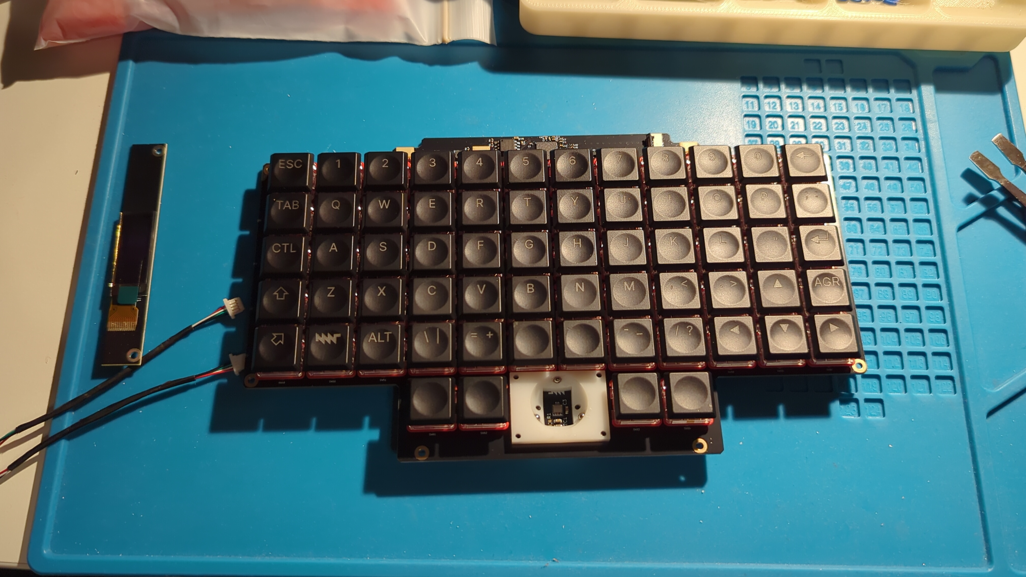

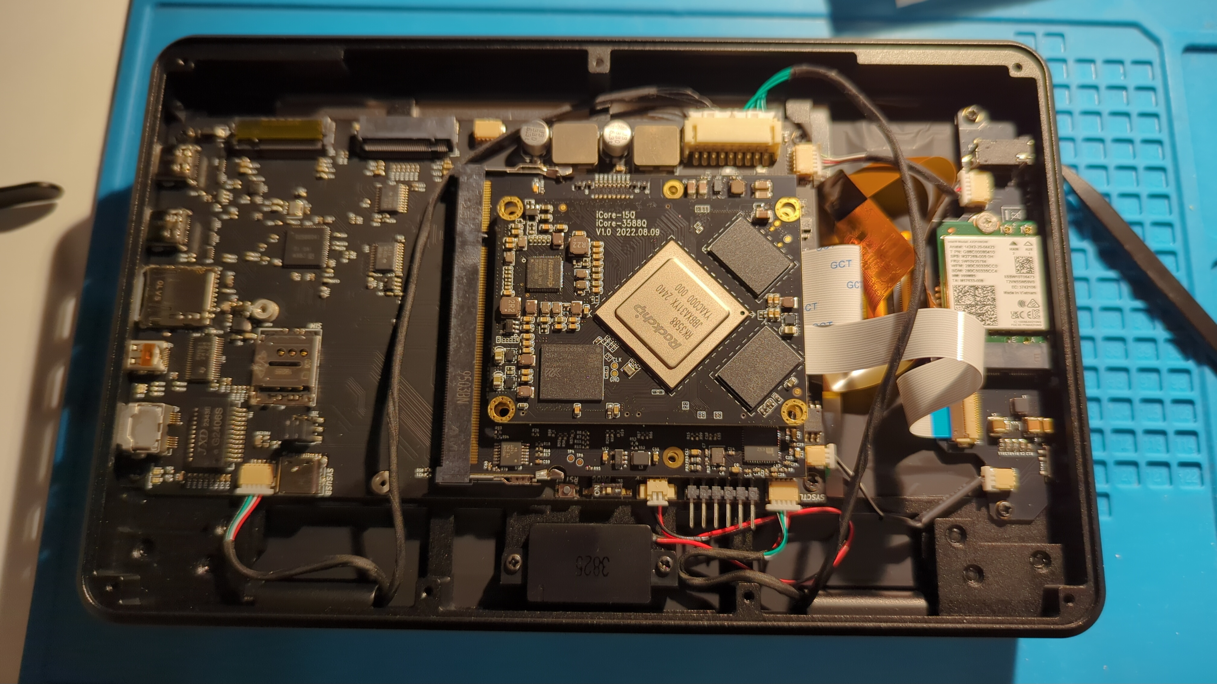
- The assembly process was fast and smooth.
- Main issues were related to flex connectors... I am never sure if they are fully seated or not.
- I have misplaced the antenna stickers to the bottom of the back panel... but not a big problem, Wi-Fi and BT works fine. I needed to tape the cables a bit and make sure screen flexi was not touching antenna cables.
- I had to reseat screen flexi as backlight was not stable.
- The trackball ball was defective, but I used a bit of "super glue" to fix it up.
- Overall it is ingenious design (e.g. use of PCB for panels and slot covers) and very high quality make. SLA prints are super nice.
Issues
No sound output on headphones
Use alsamixer and F6 to select sound card. Mess with mutting/unmutting controls there.
I was expecting the "stereo" output Pipewiere is for headphones but that is not the case. Both speaker and headphones outputs work as the same output, just headphones are muted by default on ALSA level.
Notch in the trackball
My trackball had a little notch making it stick. A bit of "super glue" and sandpaper did the trick.
On first boot screen is blank or only top half of it is working and looks corrupted
Just boot again. Looks like some initialization issue.
Screen backlight unstable
Reseat screen flexi cables. Move them away from Wi-Fi antenna cables. I used sticky tape to tape the Wi-Fi antenna cables to cover PCB and taped the screen cable so it takes less space.
SSD not showing up
Apparently not all SSDs work with this hardware. I guess some my have too much power drain at startup.
One that is not working: Samsung 980 Pro
I found working drive: SK hynix BC711 256GB M2. 2230
It needs M.2 2230 extension like this one to install: 2230 to 2280 m.2 adapter ssd.
Internals
Power
- STANDBY_3V3 - Always on (manual switch), supplied from MAX1837EUT33 regulartor (VCC 5V -> 3.3V)
- system MCU
- VCC
- USB port
- I2C pullup
- Reset pullup
- RTC
- FUSB302BMPX (USB-C with power delivery)
- Qwiic I2C
- Power rails latch (enables other power domains)
- SYSCTL UART 1 connector (keyboard)
- W25Q32JVSS (Flash?)
- system MCU
- VCC 5V - Supplied from charcher
- MAX1837EUT33 (4.5V - 24V -> 3.3V) provides STANDBY_3V3
- TPS5450DDAR when enabled via power latch provides 5V rail
- TPS5450DDAR when enabled via power latch provides 3.3V rail
- LM2830XQMFE/NOPB when enabled via power latch profides 1.1V rail
- USB_VBUS - Power form USB-C port 1 (PD port)
- VCHG Power to charger
- +5V - Enabled via latch
- AP22815A Power distribution switch; when enabled it powers USB_VBUS so any connected USB device for port 1 (PD port)
- TLV320AIC3100 Audio codec for speaker and headphones
- USB port 2 VBUS
- TPD12S521 HDMI port
- SoM (CPU card)
- TUSB8041 USB Hub
- Keyboard USB power
- (not connected) Internal USB port for flashing SYS MCU (Receptacle) - this is via do not populate (DNP) resistor so it is not connected to +5V
- +3V3 - Enabled via latch
- TXS0108EPW level shifter for modem (+1V8 -> +3V3)
- MicroSD card slot
- TPD12S521 HDMI port
- IMX Reset pullup
- DAC I2C pullup (audio)
- IMX Uart pullup
- NCV1117ST18T3G 3.3V -> 1.8V (1V8 supply)
- Ethernet LED
- USB Hub
- M2 connectors
- M2 phone modem
- MIPI-DSI Display connector
- +1V1 - Enabled via latch
- USBH_1V1 USB Hub
- +1V8 - Powered from +3V3 rail by TLV1117-18 (or ON SEMI NCV1117ST18T3G)
- MIPI-DSI Dispaly connector
- TXS0108EPW level shifter for modem (+1V8 -> +3V3)
- MicroSD card slot
- TLV320AIC3100 Audio codec for speaker and headphones
Summary:
- Main power from batteries/charger or USB-C comes on VCC 5V.
- Standby 3.3V power is regulated from the VCC 5V and is supplied to many components including charger (not used), system MCU, keyboard MCU (via UART connector), power latch, real time clock, USB-C PD chip.
- Power latch is used to enable other rails: 5V, 3.3V (both regulate VCC 5V) and 1.1V (from 3.3V).
- The 5V power is used many chips, USB power, SoM power, internal USB to keyboard.
- The 3.3V power may chips and is used for SoM UART and I2C audio chip pullups.
- The 1.1V is used only for USB Hub.
- There is also 1.8V supply that regulates from 3.3V for display, modem, MicroSD card and audio.
Interfaces
Qwiic
- Internal connector
- Powered with 3.3 standby power
- I2C to the SYS MCU (SDA0/GPIO0, SCL0/GPIO1)
Pinout:
- GND
- 3.3V (standby)
- SDA (RP2040 SDA0/GPIO0)
- SCL (RP2040 SCL0/GPIO1)
On SDA0/SCL0 we also have two chips on charger board and PD chip FUSB302BMPX.
SoM Serial Connector
They both go to the SoM card and depending on the type of card used they can be used to access boot output.
- Connector J16 - 6 pins sticking out between SYSCTL and speaker connectors
- 3.3V
- Pins left to right; assuming that the ports of the motherboard are on the right:
- S2 GND, connect to GND of your adapter
- S2 UART2_RXD, connect to TX of your adapter
- S2 UART2_TXD, connect to RX of your adapter
- S1 GND, connect to GND of your adapter
- S1 UART1_RXD, connect to TX of your adapter
- S1 UART1_TXD, connect to RX of your adapter
- Processor module card:
- RK3588 S1 @ 1500000 baud
- i.MX 8M Plus S2 @ 115200 baud
- RCM4-BPi/A311D S2 @ 115200 baud
Serial Wire Debug (SWD) on SYS MCU
On test pads:
- SWC -> TP6
- SWD -> TP5
Internal connections
SYS MCU
- I2C - SDA0/GPIO0, SCL0/GPIO1; 3.3V STANDBY
- Qwiic
- Charger board:
- MAX17320G20+ - Battery Fuel Gauge
- MP2650 - 5A Buck or Boost Charger
- UART1 TX/GPIO4, RX/GPIO5
- Keyboard
- UART2 TX/GPIO12, RX/GPIO13
- SoM as UART3_TXD/RXD -> UART0_TX/RX_M2
- USB
- RUD+/USB_DP, XUD+/USB_DM - Got to SoM but can go to internal USB-C port for direct flasing depending on USBSEL/J21 jumpers
- This is accessible from Linux as ACM UART and can be used to see debug messages from MCU and issue commands (if support is compiled in)
Battery upgrade
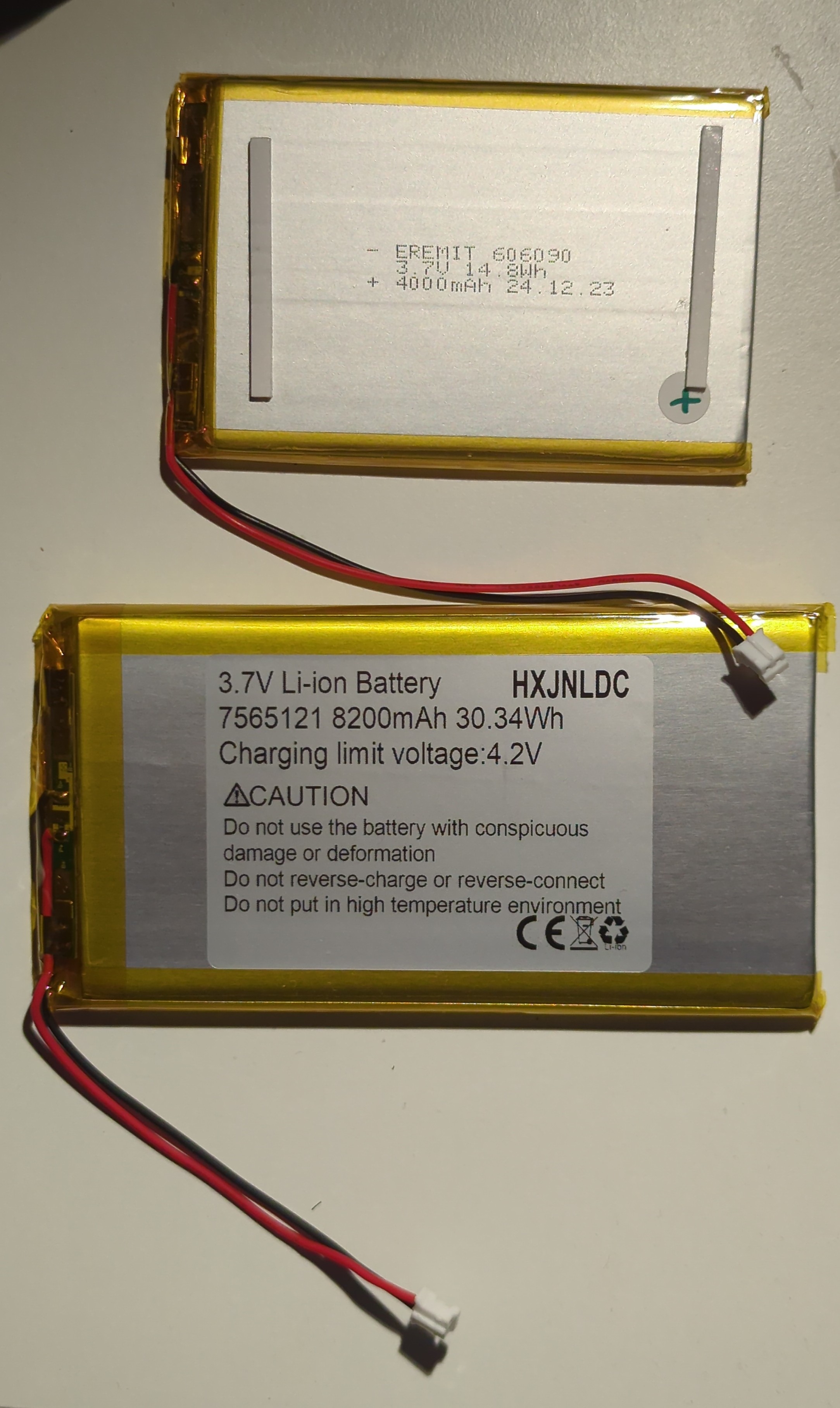

| 2x | Stock batter | Upgrade battery |
| Model | EREMIT 606090 | HXJNLDC 7565121 |
| Size | 90mm / 60mm / 6mm | 122mm / 65mm / 7.5 mm |
| Chemistry | Lithium-Polymer | Lithium-Polymer |
| Capacity | 14.8Wh (4Ah) | 30.34Wh (8.2Ah) |
| Nominal voltage | 3.7V | 3.7V |
| Discharge max continuous | 2A | 5A |
| Charging limit voltage | 4.25V | 4.2V |
| Mass | 74g | 136g |
- Connector: JST-PH 2.0mm (not included in upgraded battery) (see this and this)
- Datasheet: ePH.pdf
- Max current: 2 A
- Both batteries have protection ICs
Charging chip - MP2650
- Datasheet: MP2650GV.pdf
- 4V to 21V Operating Input Voltage (VIN) Range
- Up to 5A Configurable Input Current (IIN) Limit (Up to 45W Total Power)
- Up to 5A Configurable Charge Current (ICHARGE)
- Configurable Battery Charge Voltage Regulation (VBATT_REG) Up to 4.5V/Cell
- Up to 5V/3A USB On-The-Go (OTG)
Monitoring chip - MAX17320G20+
- Datasheet: max17320.pdf
- Battery Health + Programmable Safety/Protection
- Overvoltage (Temperature Dependent)
- Overcharge/Overdischarge/Short-Circuit Current
- Over/Undertemperature
- Undervoltage + SmartEmpty
- Battery Internal Self-Discharge Detection
- Ideal Diode Discharge During Charge Fault
- Charging Prescriptions (JEITA)
- Prequal Charge Control with CHG FET
- ModelGauge m5 EZ Algorithm
- Percent, Capacity, Time-to-Empty/Full, Age
- Cycle+™ Age Forecast
- Precision Measurement Without Calibration
- Current, Voltage, Power, Time, Cycles
- Die Temperature, 4 Thermistors ±1˚C
- Cell Balancing with Internal FETs
- SHA-256 Authentication
- Nonvolatile Memory for Stand-Alone Operation
- History Logging, User Data (84 Bytes)
Firmware
pocket-reform-sysctl-fw/src/sysctl.c void charger_init()
  // 2A max charge current, assumes 4000mAh cells.
  mps_reg_limits.charge_current = 1<<5 | 1<<3;
  // set all current limits to 500mA (should always be safe)
  int current_limit = 1<<3 | 1<<1;
  mps_reg_limits.input_i_limit1 = current_limit;
  mps_write_buf(MPS_REGSTART_LIMITS, sizeof(mps_reg_limits.all_regs), mps_reg_limits.all_regs);
  mps_read_buf(MPS_REGSTART_LIMITS, sizeof(mps_reg_limits.all_regs), mps_reg_limits.all_regs);
mps_write_byte(0x0F, current_limit); // Input Limit 2- Charging current limit is 2A by default hard-coded in the firmware.
- Upgraded batter can go up to 5A and charger chip can also go up to 5A but PH connectors only do 2 A max so can't increase charging current.
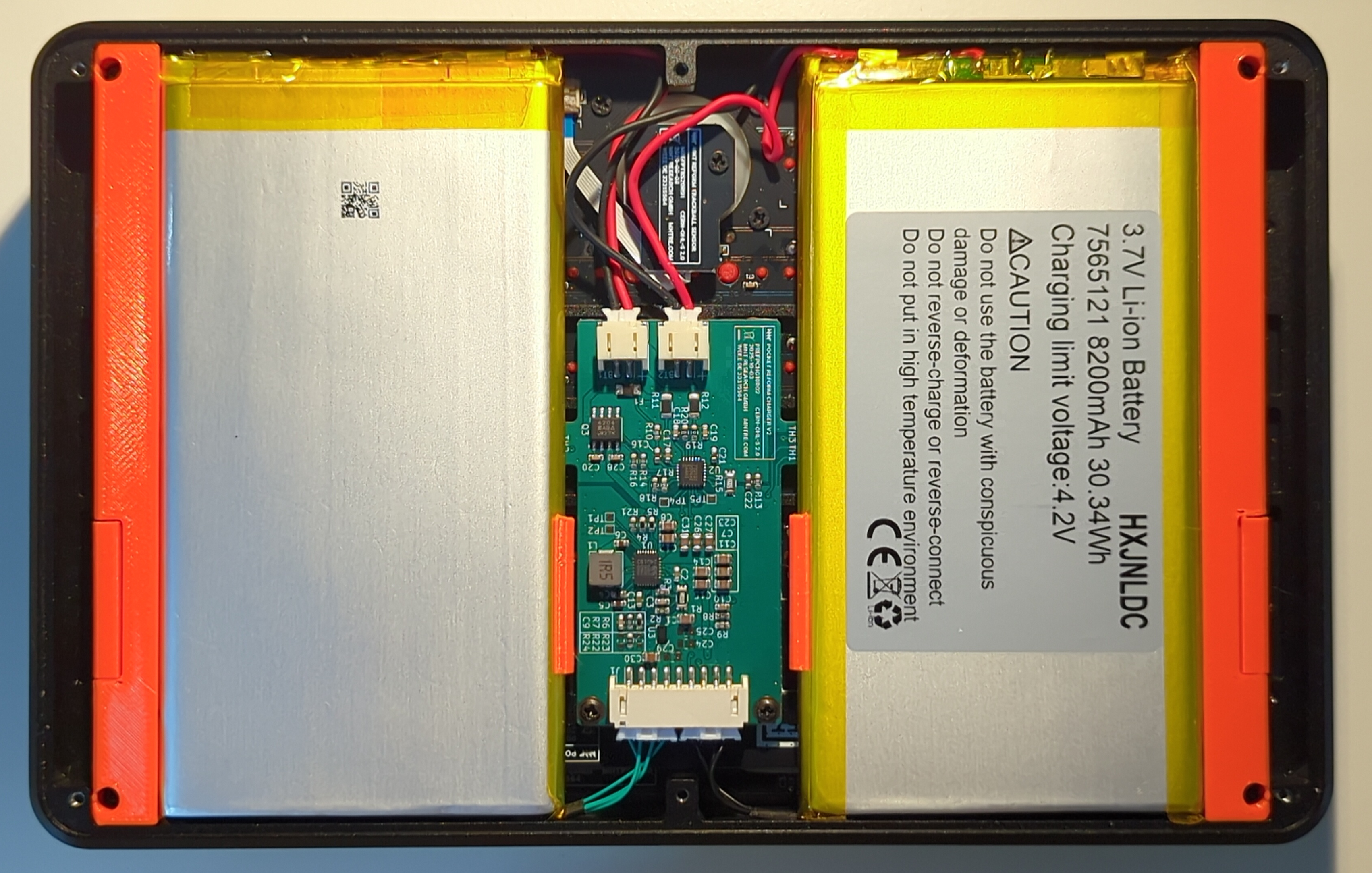
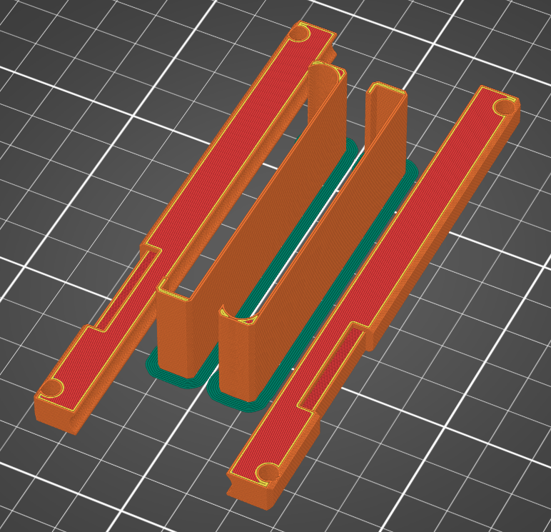
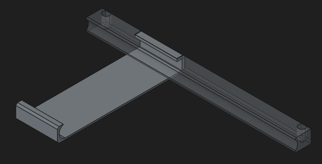
Upgrade battery holding brackets
- FreeCAD: bat_holder.FCStd
- STL:
Bootloader barebox
Installation
Always check if and of paths are correct. Use lsblk to verify.
Setup SD card
sudo dd if=pocket-reform-system-rk3588.img of=/dev/mmcblk0 bs=1M oflag=direct status=progress
sudo dd if=barebox-mnt-pocket-reform-rk3588.img of=/dev/mmcblk0 seek=64 oflag=direct status=progress
Test bootloader from SD card
- Boot from SD card
- Make backup of MMC bootloader:
sudo dd if=/dev/mmcblk0 bs=1M count=10 of=emmc-backup.bin - Erase MMC bootloader first stage to force boot form SD card bootloader:
sudo dd if=/dev/zero bs=512 seek=64 of=/dev/mmcblk0 count=2 oflag=direct - Turn off and on again.
-
Press
mto get barebox boot menu -
Press
2Detect bootsources and test if you can boot your normal OS.
From main OS install new bootloader to MMC
sudo dd if=/dev/mmcblk1 of=/dev/mmcblk0 bs=1M count=10 oflag=direct- Turn it off.
- Take out SD card.
- Boot again - it should boot your normal OS using barebox.