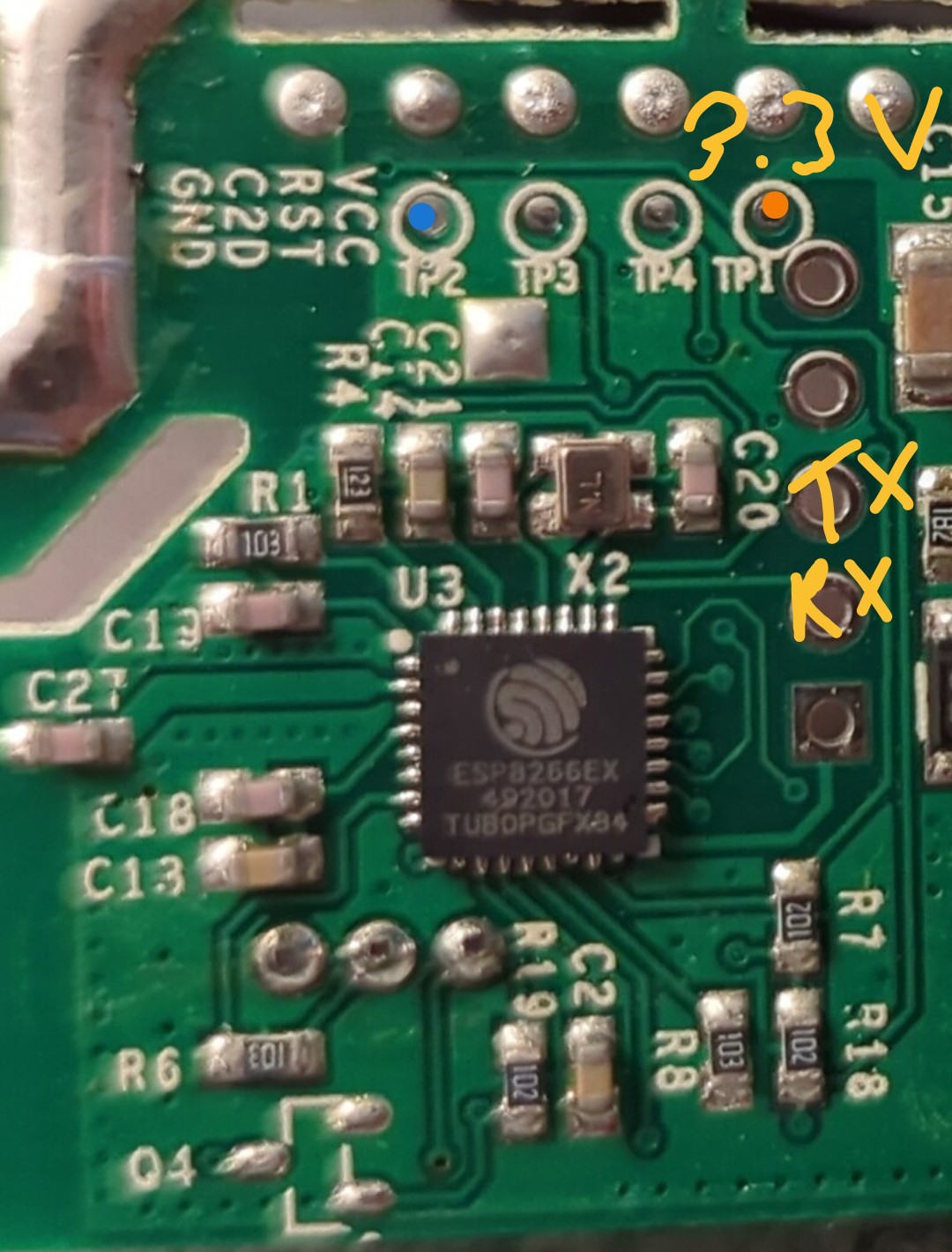
Smart switch ESP 8266EX
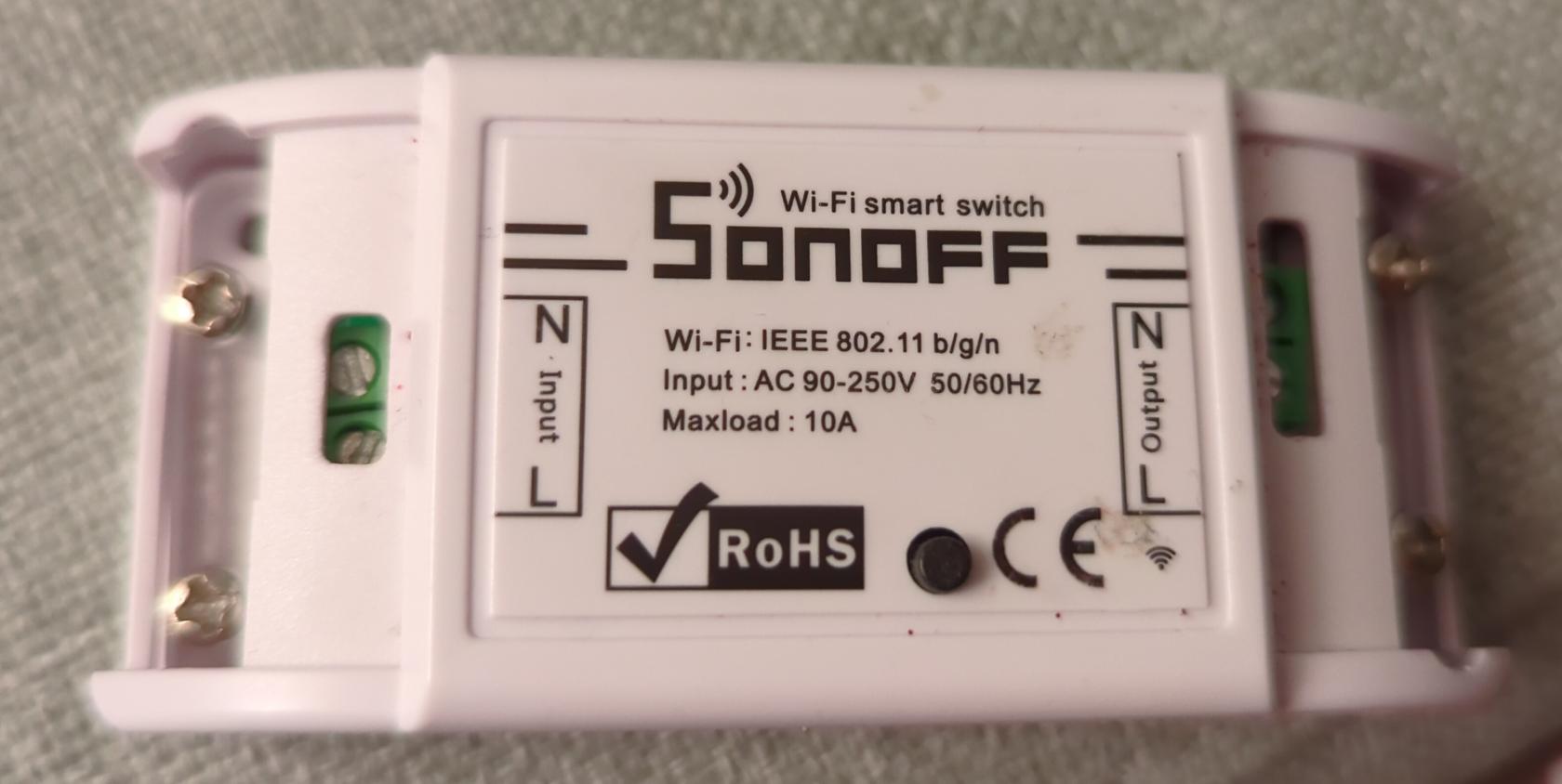
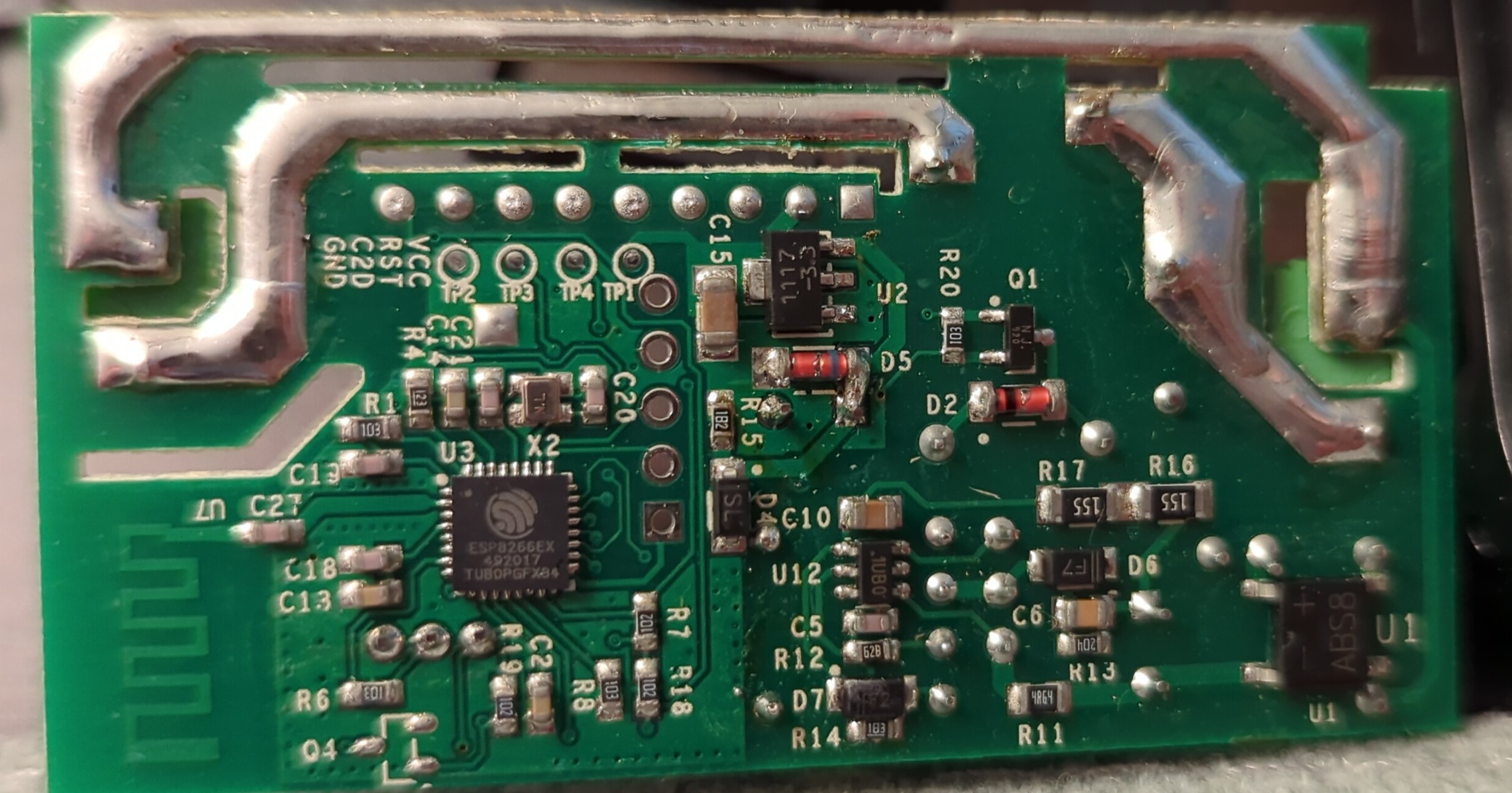
Input for the board is from mains. It is then rectified and transformed down to 3.3V via DS1117 regulator to power the ESP8266EX chip and the relay that switches the mains relay.
Marked are 3.3V VCC and GND. The ESP8266EX UART-0 is on marked points TX and RX.