RC2014 Schematics - Pro Kit
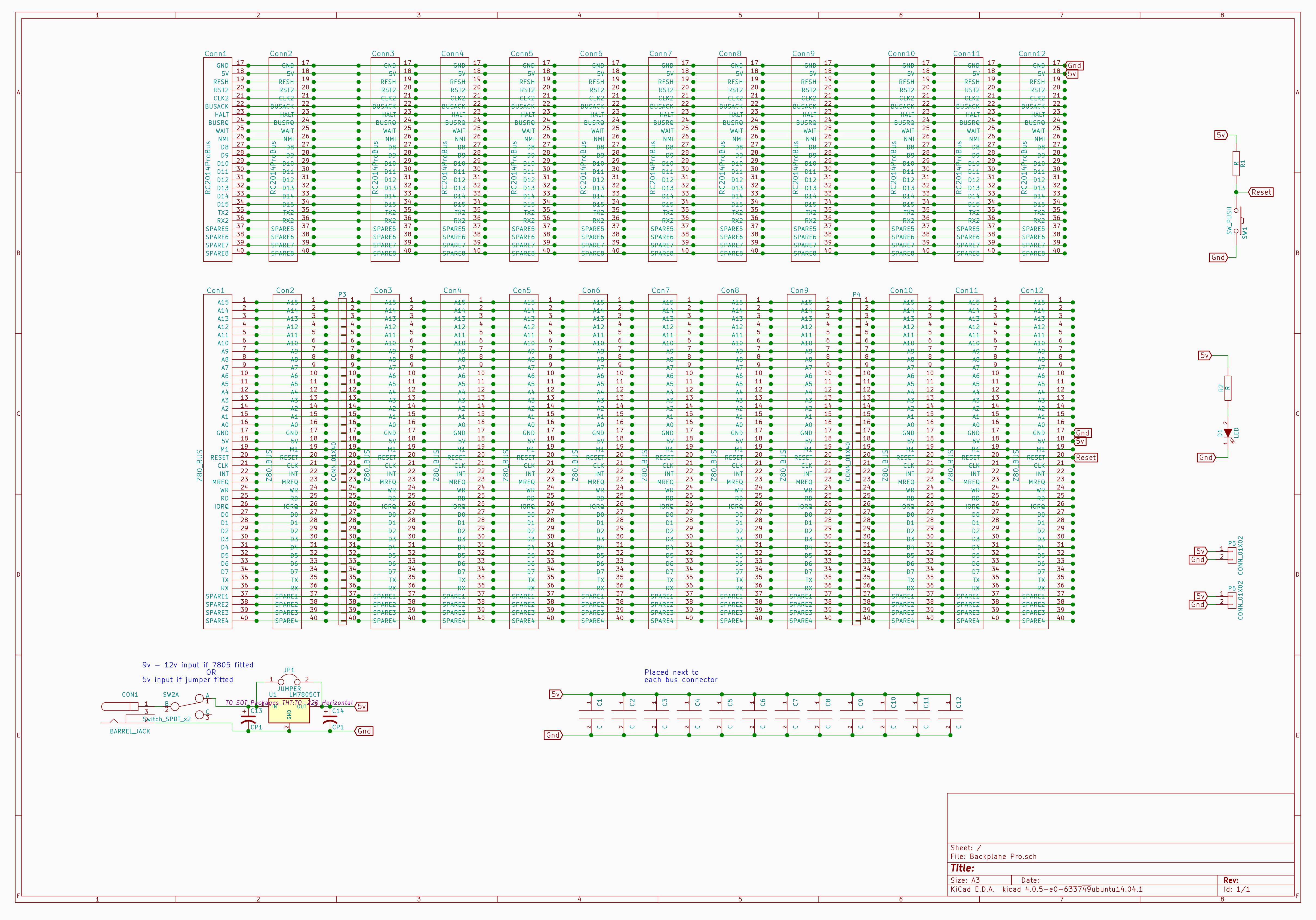
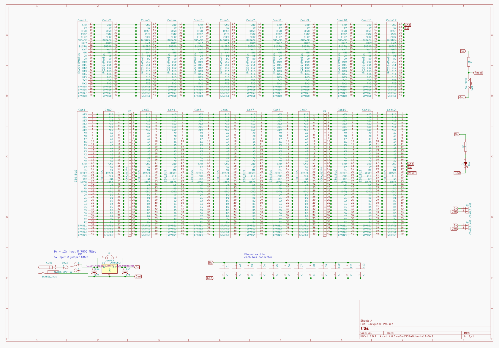
Pro Backplane
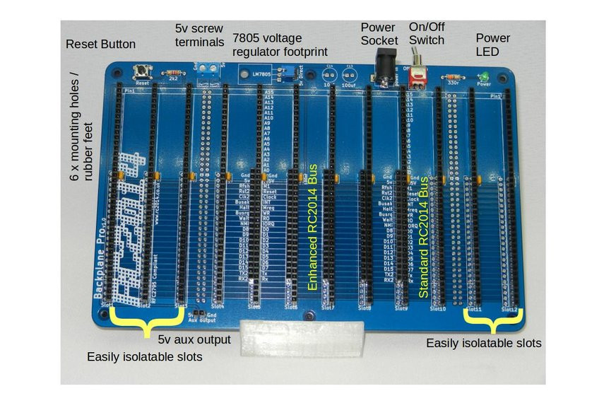
1   RC2014 BACKPRO PCB
1   2.1mm Power Jack
12  40 Way SIL Socket
5   20 Way SIL Socket
12  100nf
1   Tactile Switch
1   2k2 Resistor
1   3mm Green LED
1   330r resistor
1   Jumper
1   USB Barrel Lead
5   40x2 RA Header
1   RA Toggle Switch
1   2 Screw Terminal
6   Rubber Foot
1   2 pin RA Header
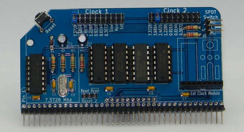
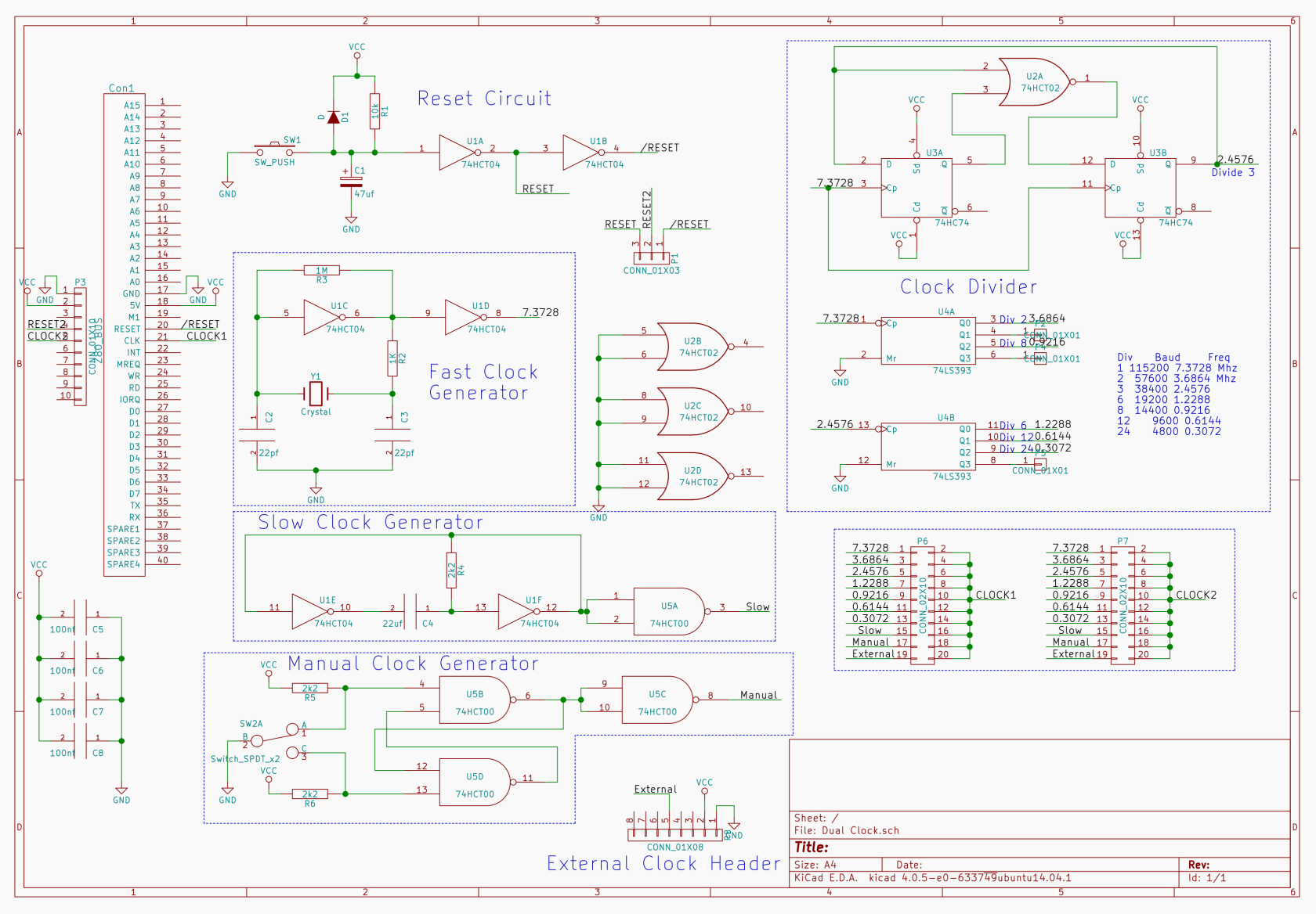
 Dual Clock
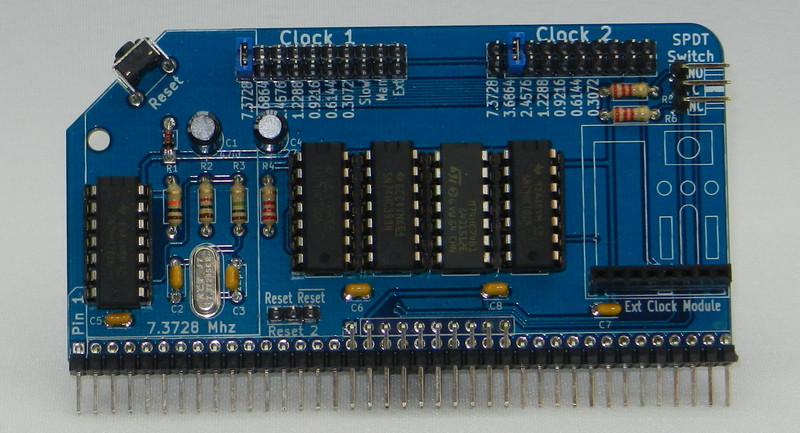
	Dual Clock Multi Speed - Enhanced Bus

1	RC2014 DUAL CLOCK PCB
1	2x40 pin RA Header
5	14 pin narrow DIL socket
1	74HCT04
1	74HCT00
1	74LS393
1	74HCT74
1	74LS02
1	7.3728 Mhz Xtal
2	22pf ceramic cap
4	100nf
1	1M resitor
1	1k resistor
1	10K resistor
3	2K2 resistor
1	47uf 25v electrolytic
1	22uf 25v electrolytic
1	1N4148
1	RA Tactile Switch
5	10 pin header
1	8 Way SIL Socket
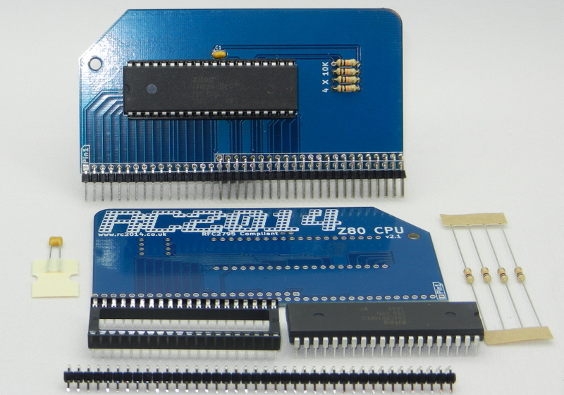
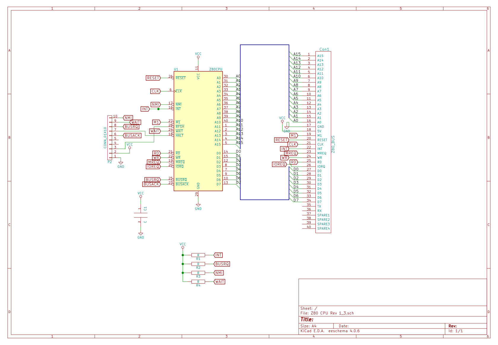
CPU

1   Z80 CPU 2.1 PCB
1   2x40 pin DIL socket
1   Zilog Z80 CPU
1   40 pin RA Header
1   100nf
4   10k
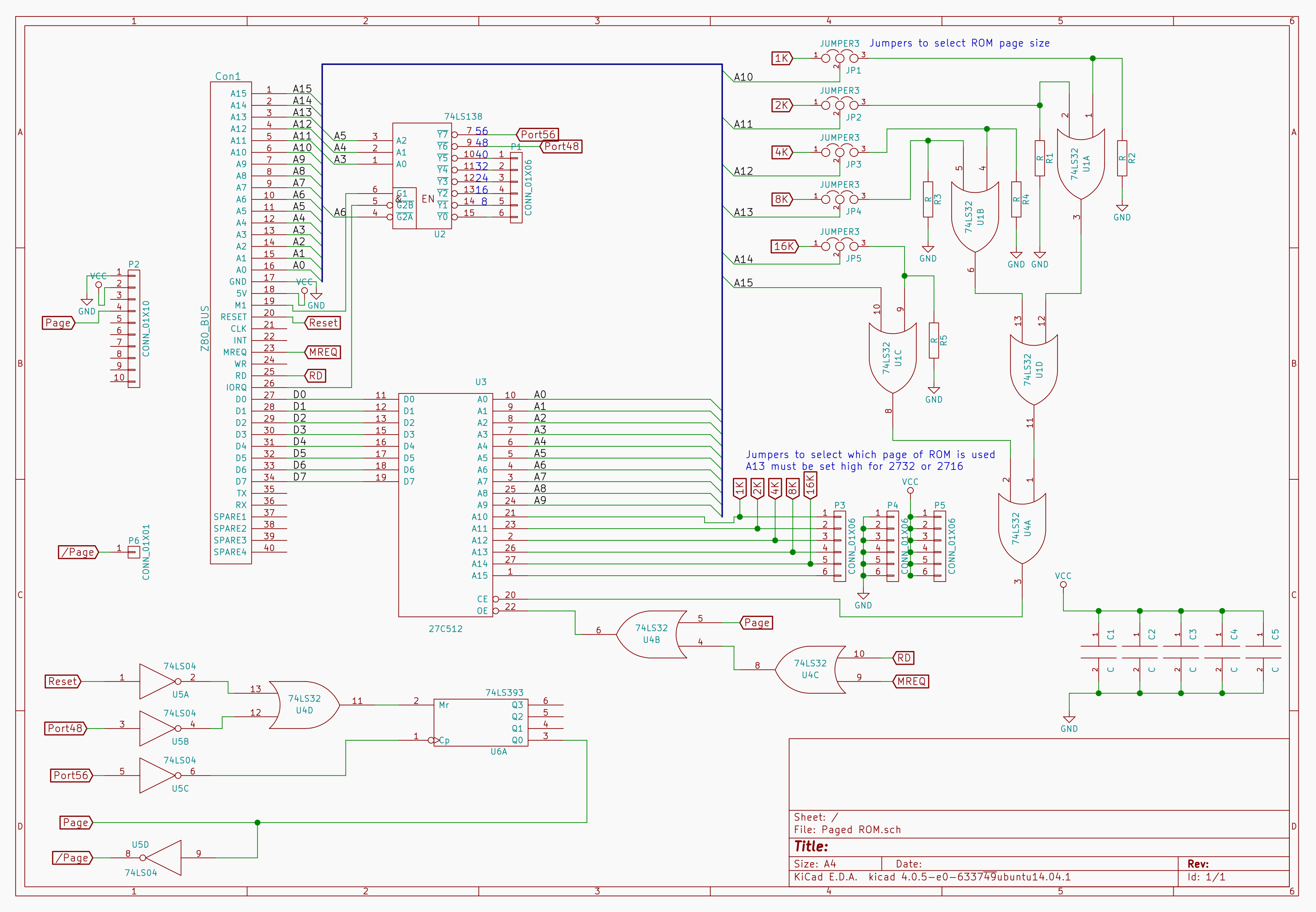
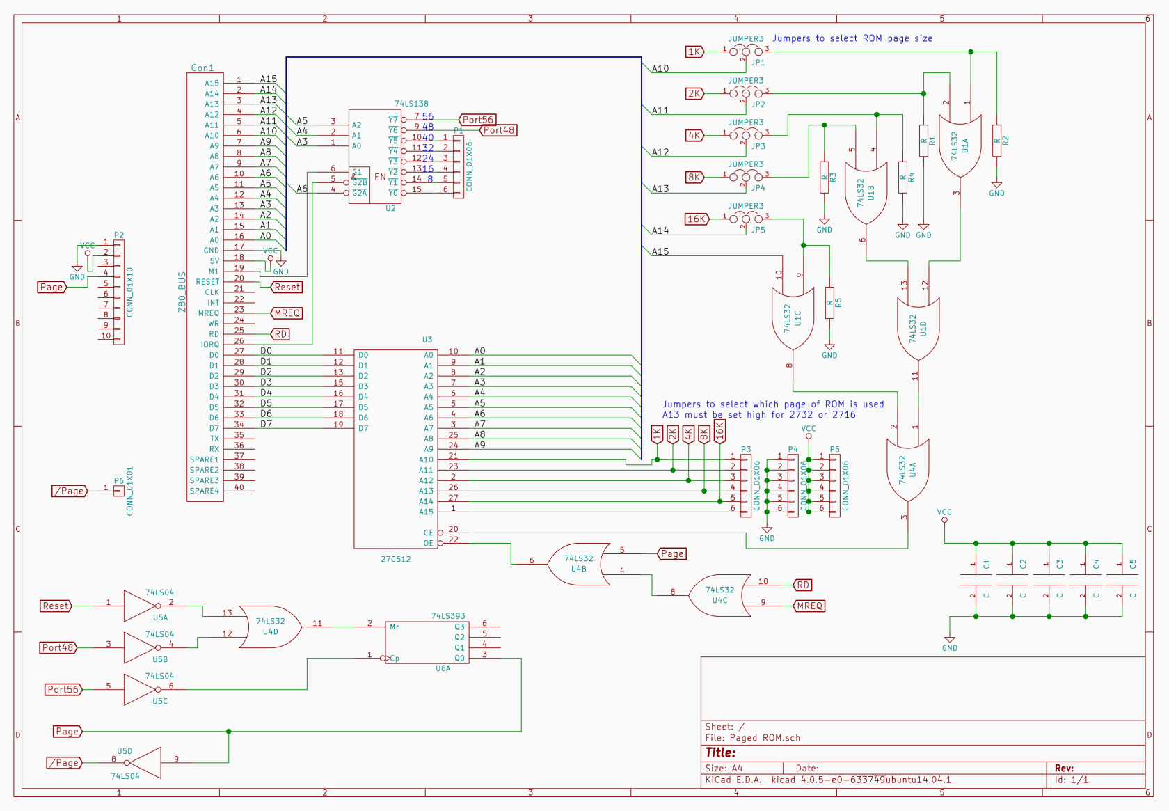
Pageable ROM
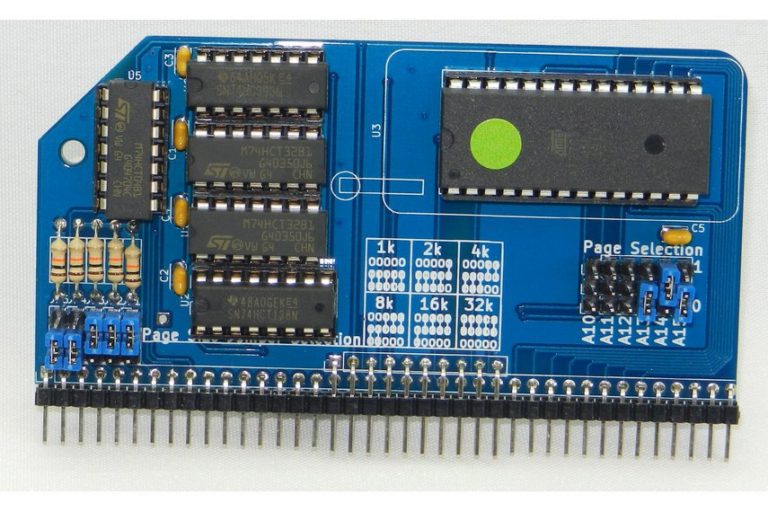
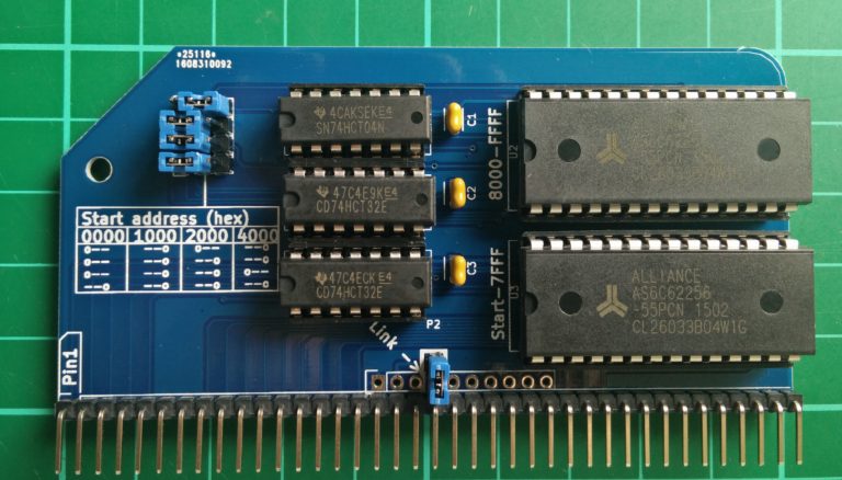
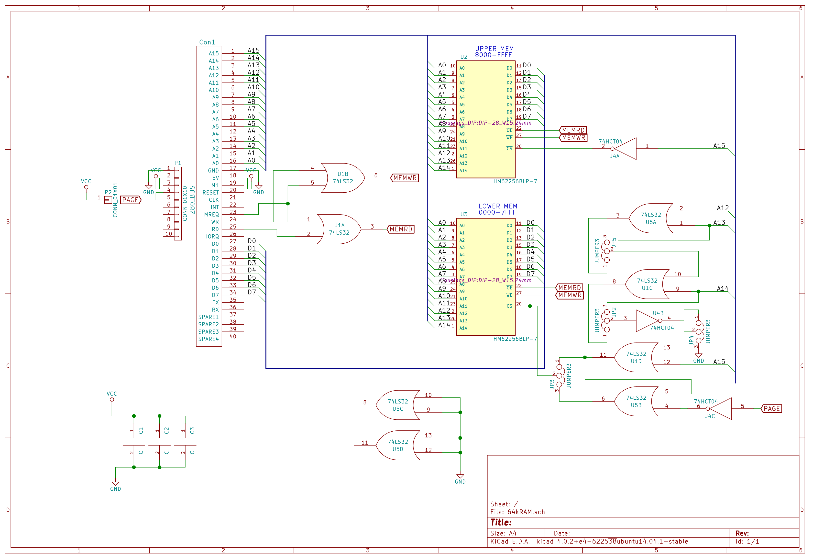
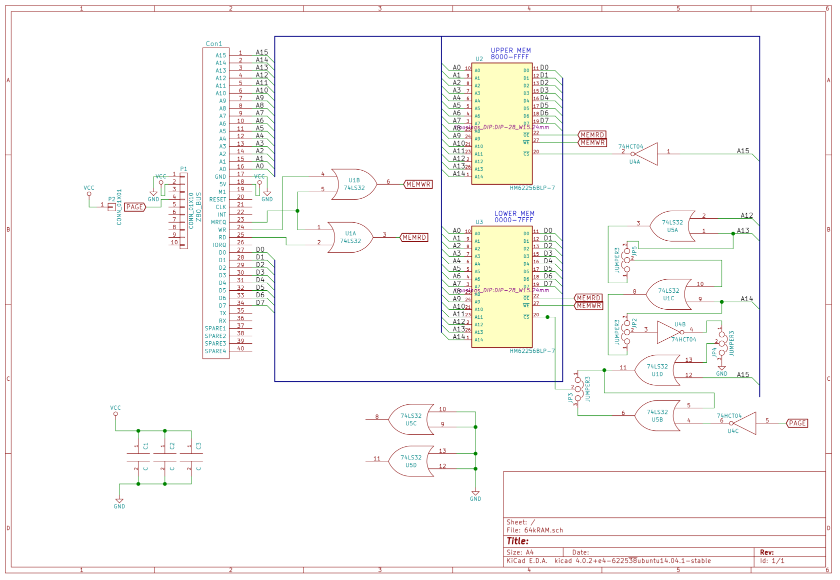
64k RAM

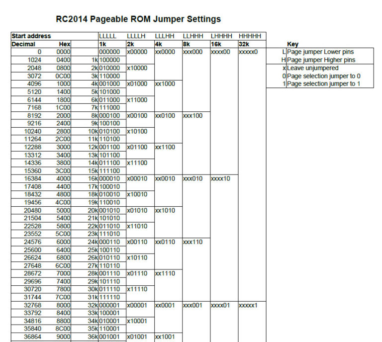
Jumper settings for the start address are as follows

0x0000  0x1000  0x2000  0x4000
0==     ==0     0==     ==0
0==     ==0     ==0     ==0
0==     ==0     ==0     0==
==0     ==0     ==0     ==0
SIO/2 Serial Module
Compact Flash Module v2