
RC2014 Schematics - Pro Kit
Official
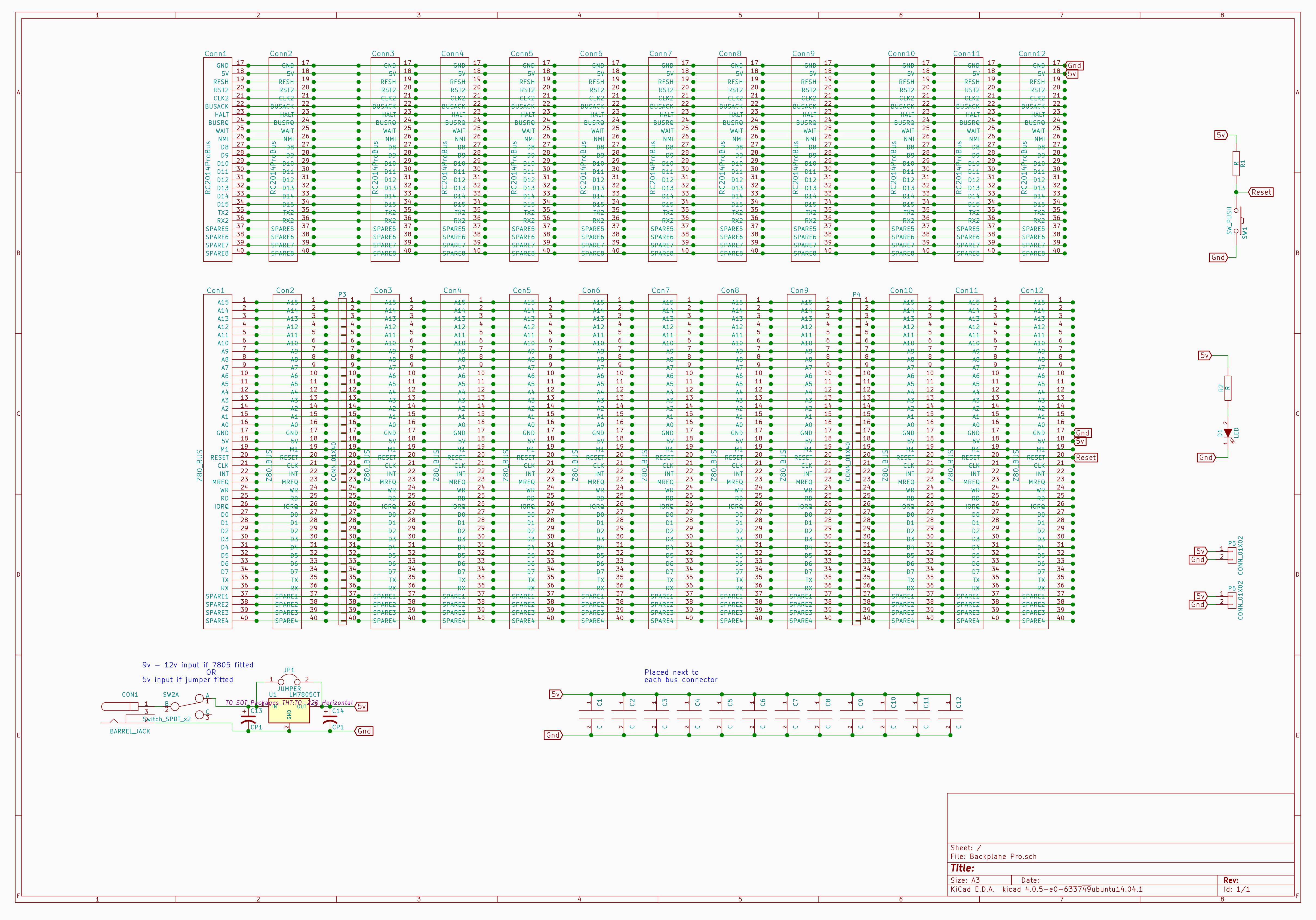
store (EU): https://z80kits.com/shop/rc2014-pro/Pro Backplane
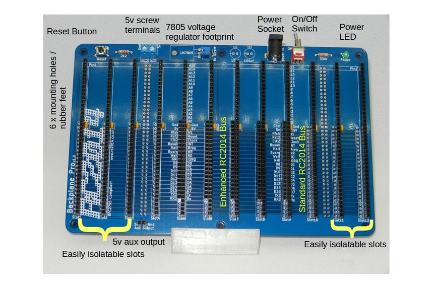
1 RC2014 BACKPRO PCB
1 2.1mm Power Jack
12 40 Way SIL Socket
5 20 Way SIL Socket
12 100nf
1 Tactile Switch
1 2k2 Resistor
1 3mm Green LED
1 330r resistor
1 Jumper
1 USB Barrel Lead
5 40x2 RA Header
1 RA Toggle Switch
1 2 Screw Terminal
6 Rubber Foot
1 2 pin RA Header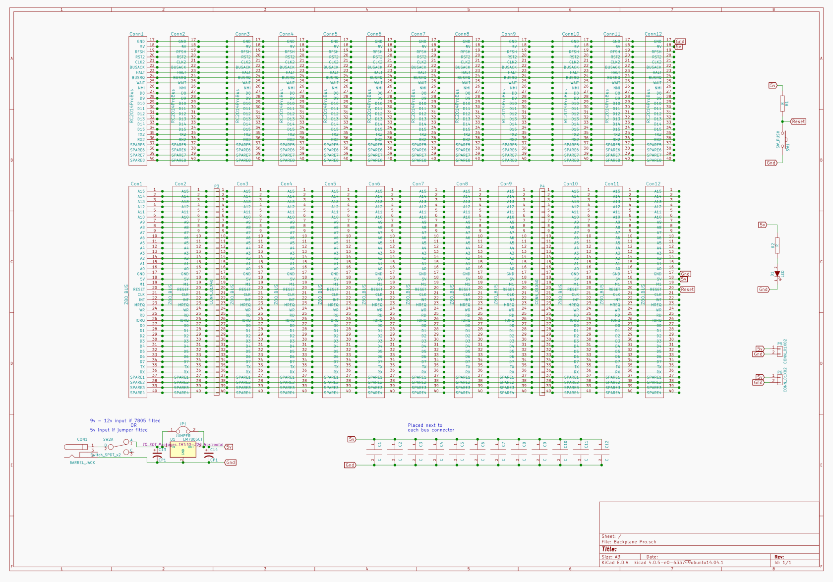 Dual Clock
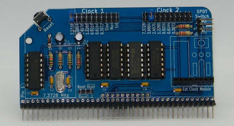
	Dual Clock Multi Speed - Enhanced Bus

1	RC2014 DUAL CLOCK PCB
1	2x40 pin RA Header
5	14 pin narrow DIL socket
1	74HCT04
1	74HCT00
1	74LS393
1	74HCT74
1	74LS02
1	7.3728 Mhz Xtal
2	22pf ceramic cap
4	100nf
1	1M resitor
1	1k resistor
1	10K resistor
3	2K2 resistor
1	47uf 25v electrolytic
1	22uf 25v electrolytic
1	1N4148
1	RA Tactile Switch
5	10 pin header
1	8 Way SIL Socket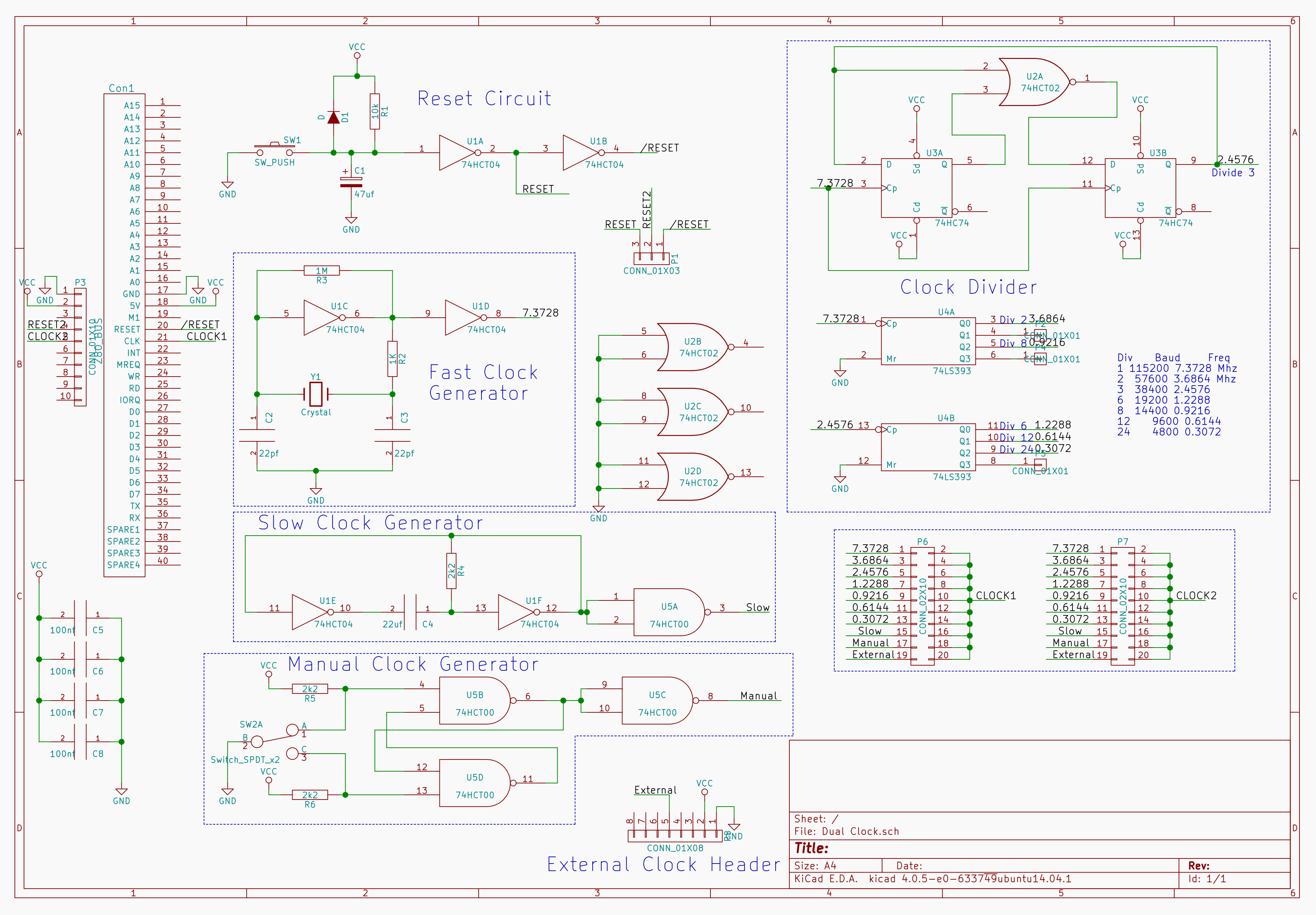
CPU
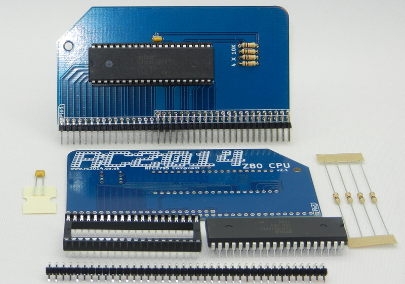
1   Z80 CPU 2.1 PCB
1   2x40 pin DIL socket
1   Zilog Z80 CPU
1   40 pin RA Header
1   100nf
4   10k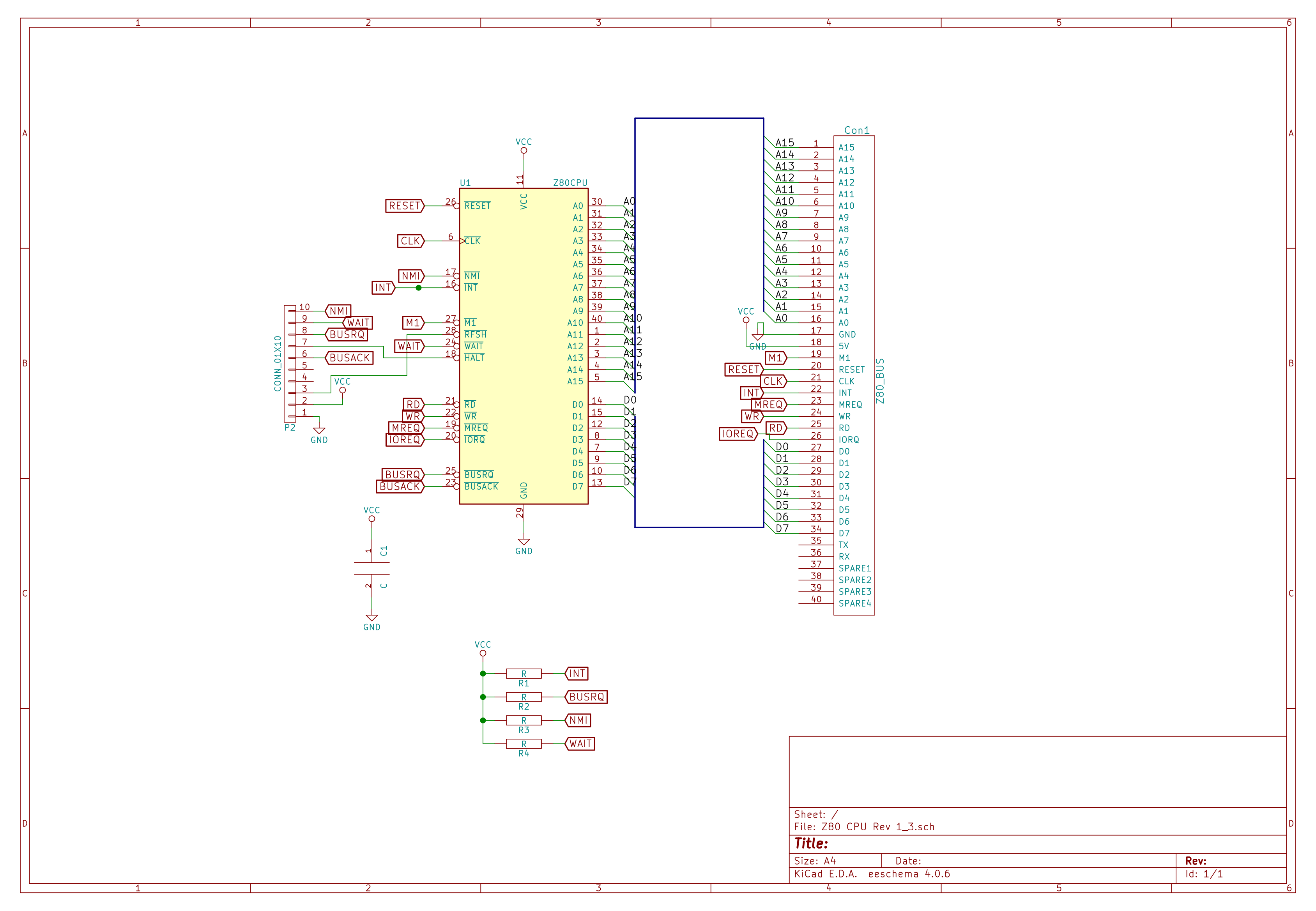
Pageable ROM
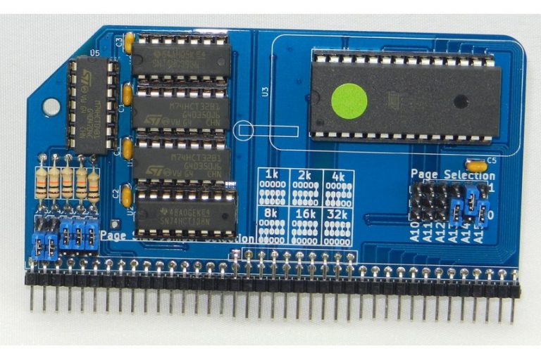
1   RC2014 PAGEROM PCB
1   28 pin wide ZIF socket
1   2x40 pin RA Header
11  3 pin header
1   10 pin header
8   Jumper
1   16 pin narrow DIL socket
4   14 pin narrow DIL socket
5   100nf
1   74LS393
1   74HCT04
2   74LS32
1   74HCT138
5   10K resistor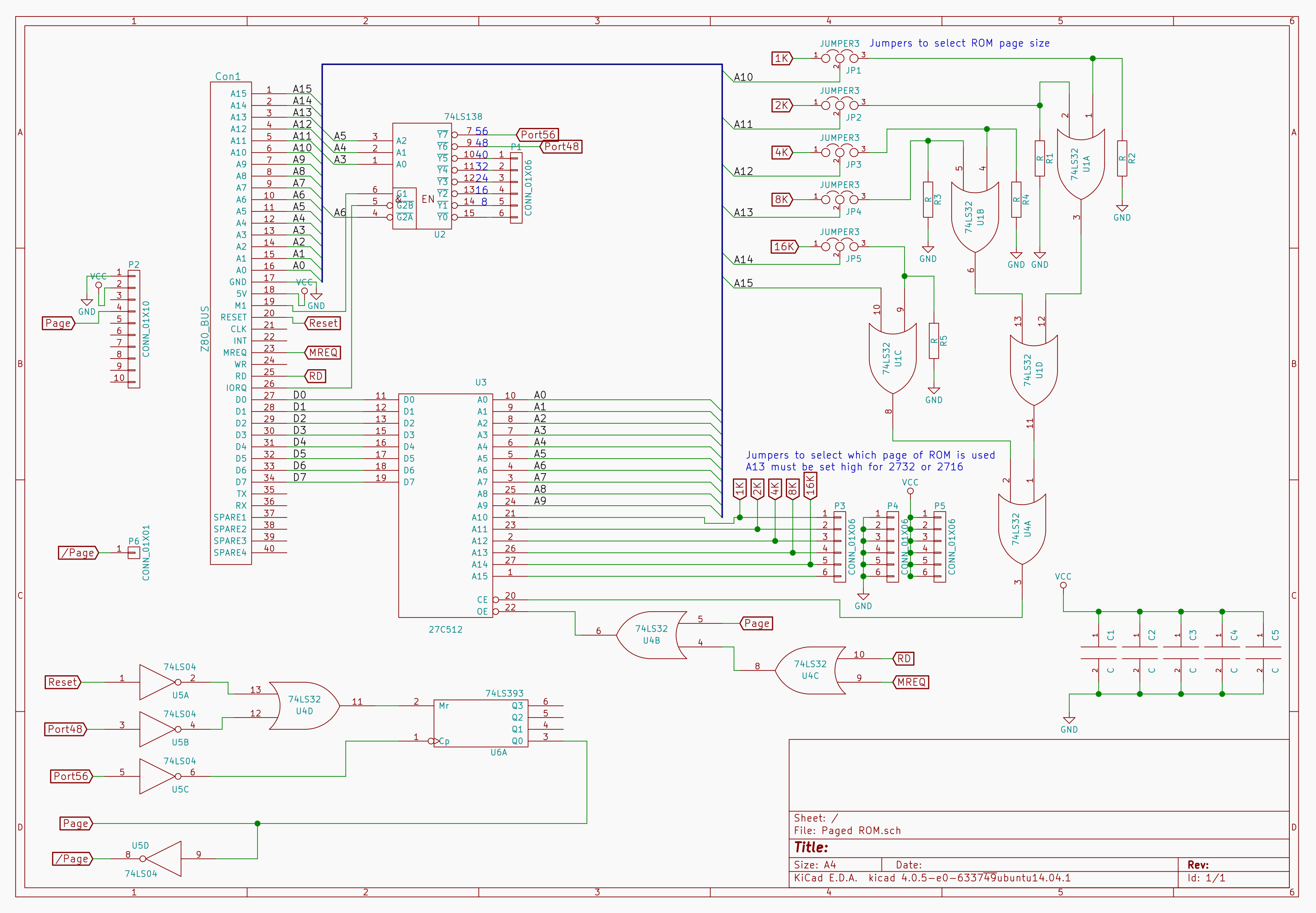
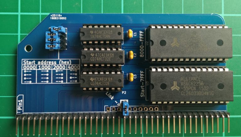
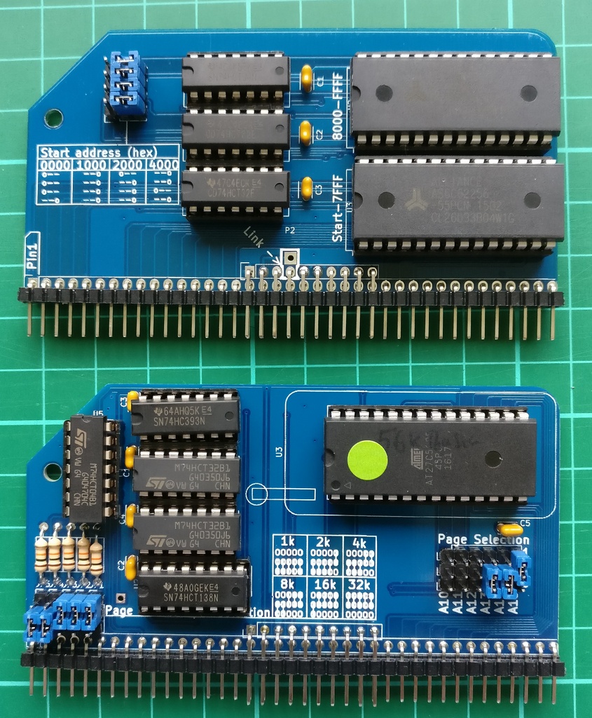
64k RAM
CP/M: The Page Pin from the ROM needs to be connected to the Page Pin on the RAM. If you have the Backplane Pro and have installed the double header pins supplied with that then nothing further needs to be done.
1   2x40 pin RA Header
2   28 pin wide DIL socket
3   14 pin narrow DIL socket
2   74LS32
1   74LS04
2   62256 RAM
3   100nf capacitors
4   3 pin header
4   jumper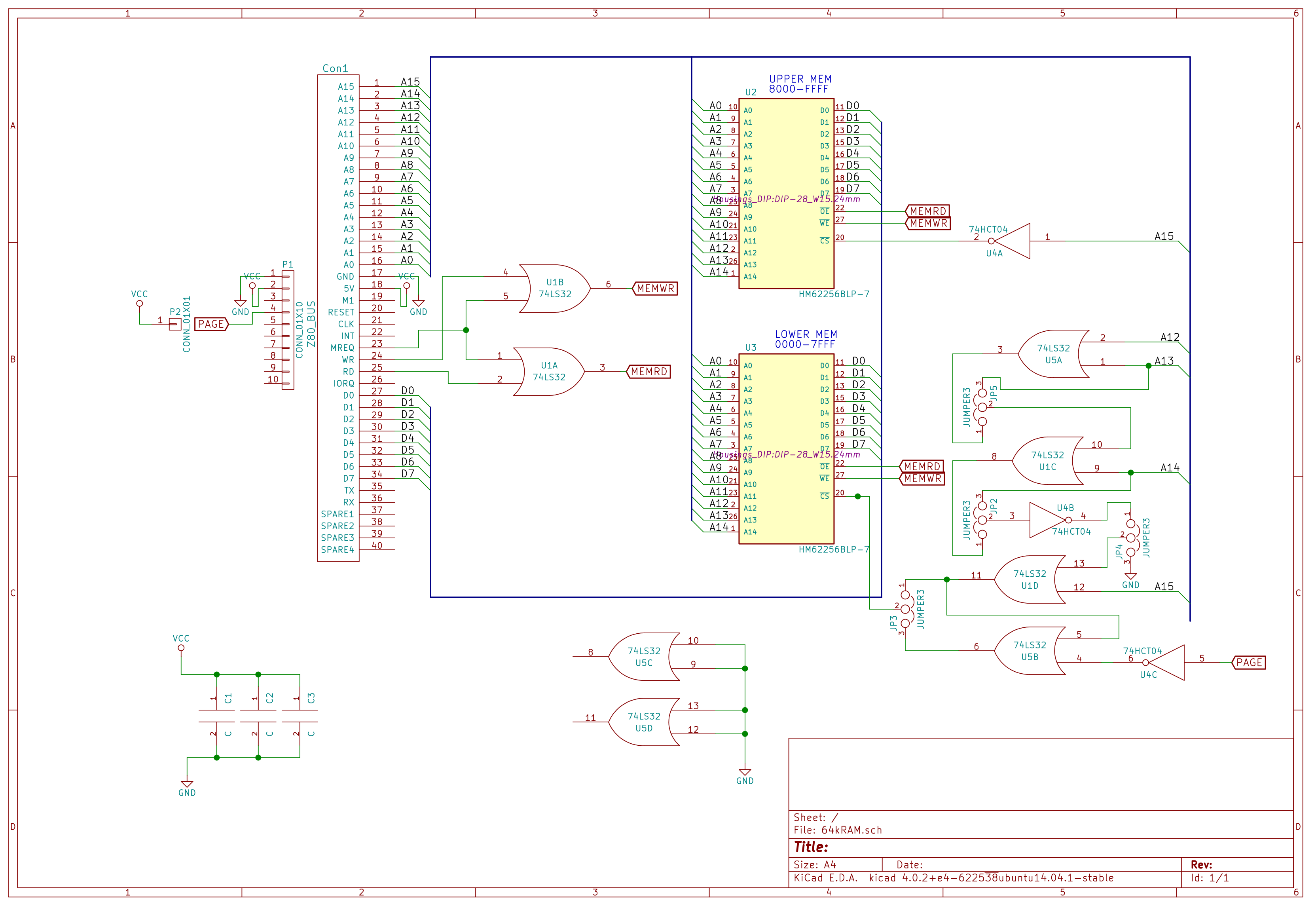
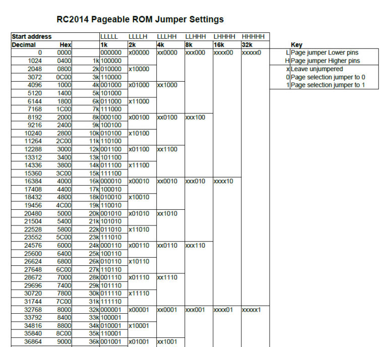
Jumper settings for the start address are as follows

0x0000  0x1000  0x2000  0x4000
0==     ==0     0==     ==0
0==     ==0     ==0     ==0
0==     ==0     ==0     0==
==0     ==0     ==0     ==0
SIO/2 Serial Module
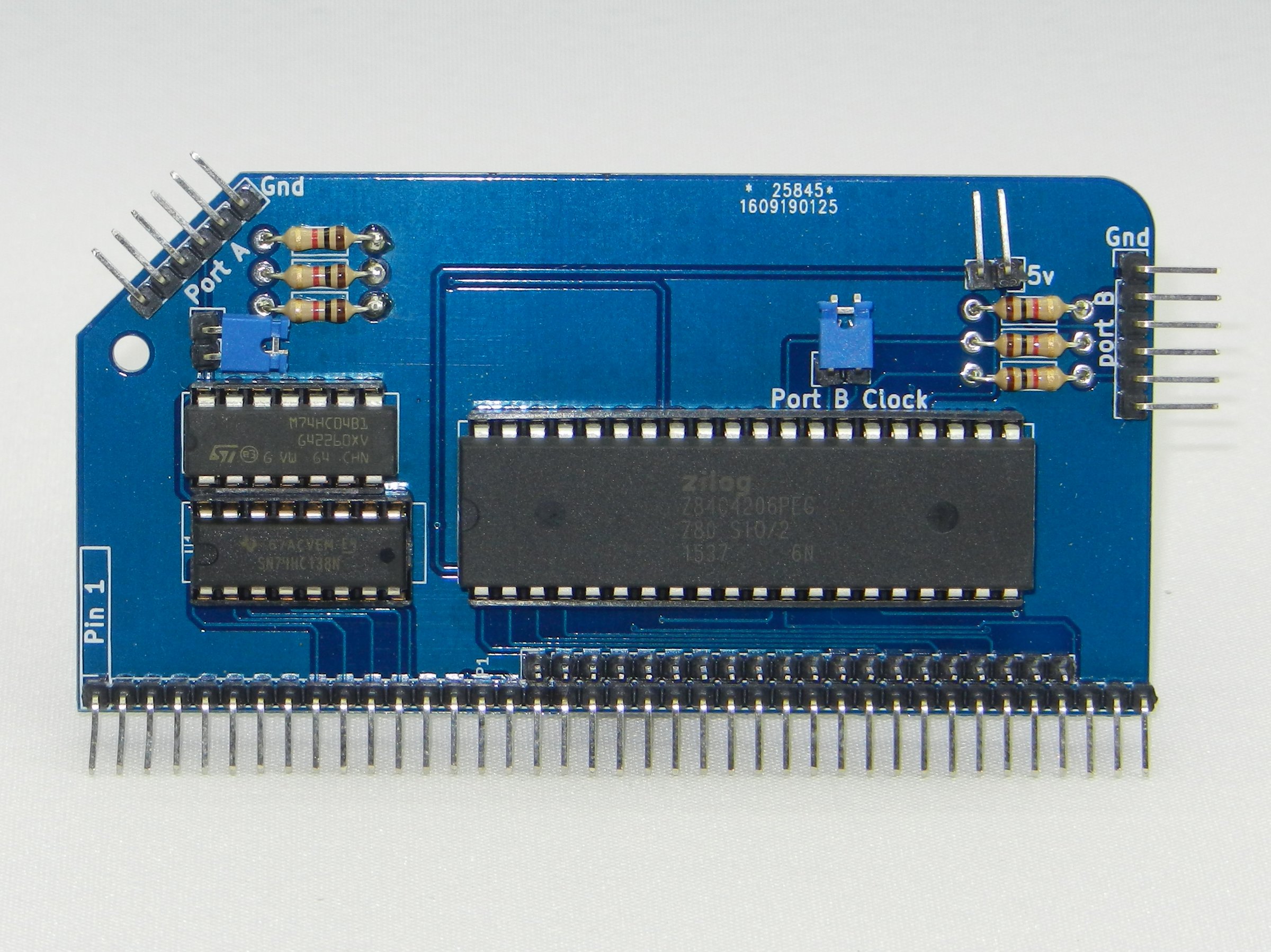
1	RC2014 DUAL SERIAL PCB
1   40x2 RA Header
1	40 pin wide DIL socket
1	16 pin narrow DIL socket
1	14 pin narrow DIL socket
1	SIO/2
1	74HCT138
1	74HCT04
6	1k resistor
2	6 pin RA Header
3	2 pin RA Header
3	Jumper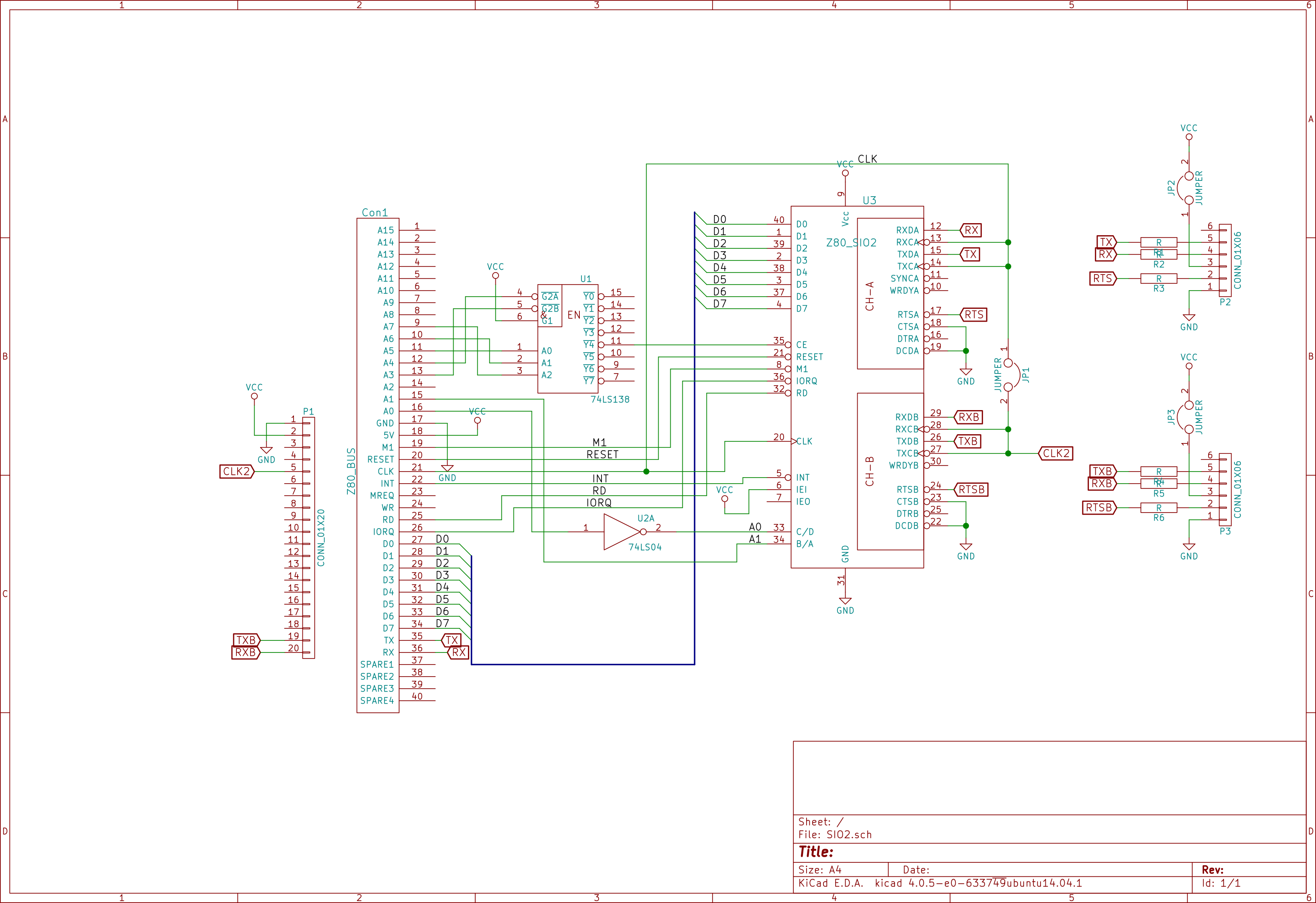
Compact Flash Module v2
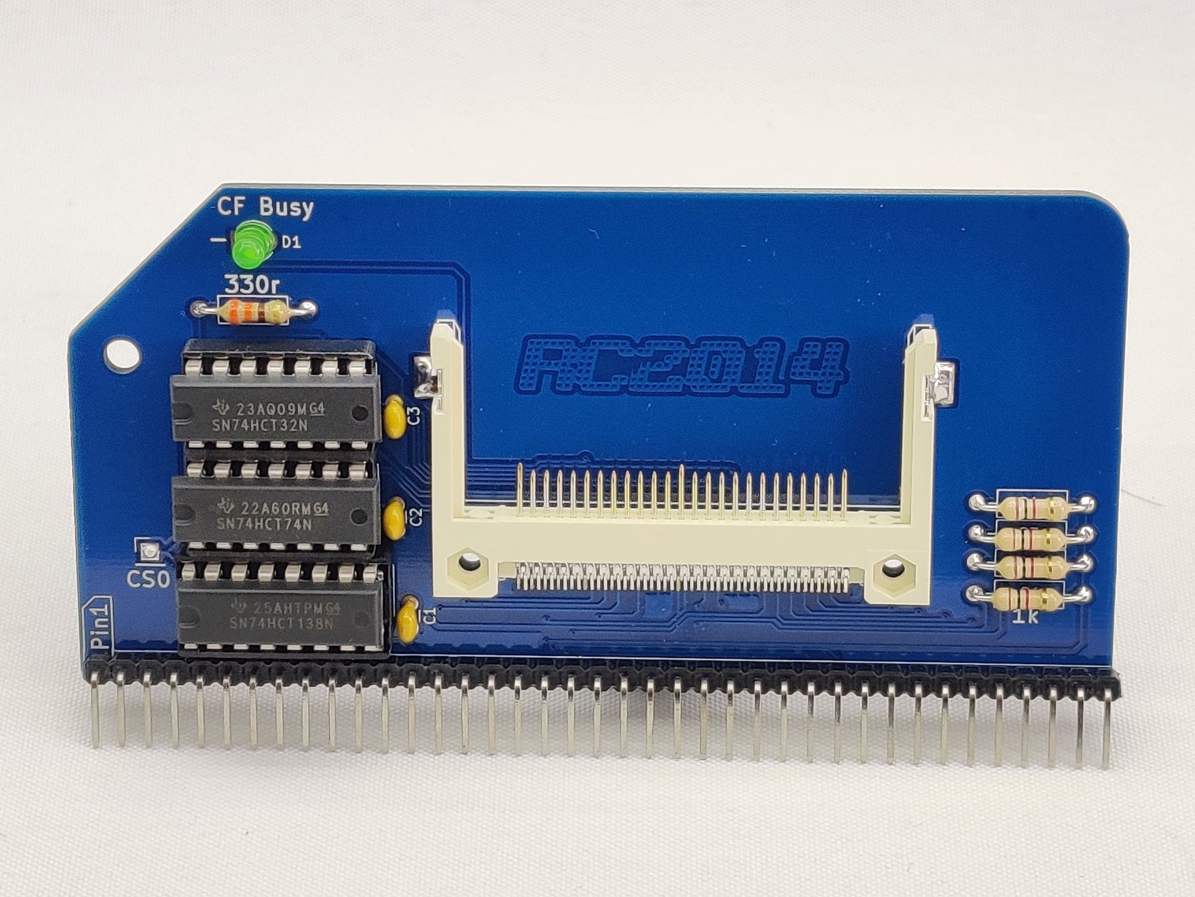
1	RC2014 CFLASH PCB
1	Compact Flash Socket
1	40 pin RA Header
1	16 pin narrow DIL socket
2	14 pin narrow DIL socket
3	100nf
1	74HCT138
1   74HCT32
1   74HCT74
1	330R resistor
4	1K resistor
1	3mm Green LED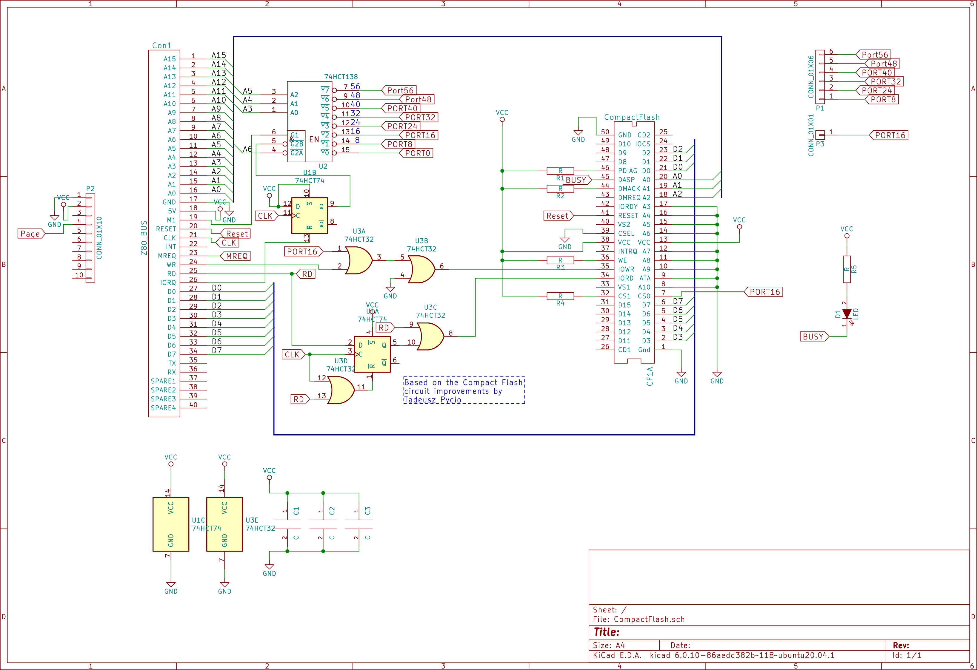
Configuration
All four jumers to right hand setting.
Top 3 jumpers set start address to 0x0000.
Bottom jumper sets lower 32k to be paged in or out from Pageable ROM board.Note that the B option for BASIC will not work with this hardware set up. If you want to use BASIC from ROM set the A15 Page Selection jumper to 0. A better solution though is to download a copy of mbasic or BBC Basic to CP/M, which then allows you to use the compact flash card for storage